This thread has been locked.

If you have a related question, please click the "Ask a related question" button in the top right corner. The newly created question will be automatically linked to this question.

BQ25570: VSTOR could not be charged again when I used BQ25570 connected with TPS22860 to control the power supply to the load

Part Number: BQ25570
Other Parts Discussed in Thread: TPS22860,

Hi,

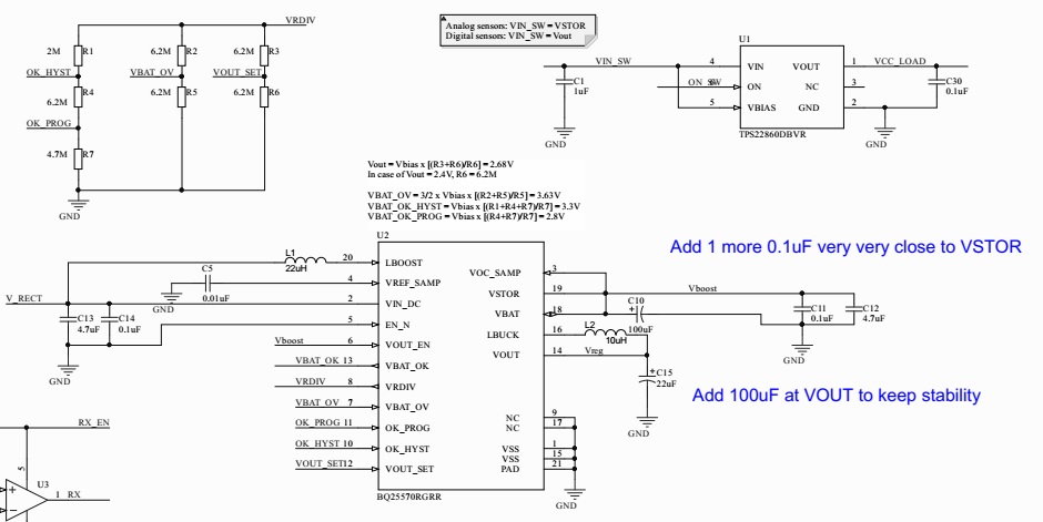
My schematic is as follows. My design includes 2 phases:

- Phase 1: When VSTOR reaches 3.3V (the upper threshold), VOUT and VBAT_OK are activated (2.4V and 3.3V, respectively). At that time TPS22860 is switched on. VCC_LOAD will be connected to VOUT to supply power to the load.

- Phase 2: The load consumes power and VSTOR decreases to 2.8V (the lower threshold). At that time, VOUT and VBAT_OK are deactivated (i.e. 0V). TPS22860 is off, no power is to be supplied to the load. 

- Phase 1 starts over.

My problem was that, Phase 1 could not restart. VSTOR remained at a certain level (~2.2V) lower than the lower threshold and never be charged again. BUT, if I used VSTOR as the input of TPS22860 (meaning VOUT was not used anymore), everything was exactly what I wanted. Phase 1 & Phase 2 repeated perfectly, except VCC_LOAD was connected to VSTOR instead of VOUT.

Could anybody suggest me any solution to use VOUT as explained above? Thank you very much.

  • Minh,

    Could you connect a DC supply to the VIN_DC pin to make sure there is enough current to restart phase1?

    Also could you show plots of VINDC, VSTOR, VRDIV when phase 1 is trying to restart? Any oscillation?

    Since the voltage when you are starting phase 1 is high, you will directly go to main boost operation mode. note that VIN will have to be present to start the system.

    Regards,

    Gautham

  • Dear Gautham,

    Thank you very much for your response. Please find below the VSTOR and VCC_LOAD (meaning the VOUT of TPS22860) captured by oscilloscope. You can see VSTOR remained 2.3V. I monitored it in about 15 minutes and VSTOR could not charge up.

    I tried DC voltage as the input source of BQ25570, and experienced the same problem if Vin ~<1V. I've not tried with larger input power.

    I suppose my problem fall in the reason you mentioned. But when I used VSTOR to supply power to the load (meaning VIN_SW = VSTOR), everything was fine, even VSTOR was not discharged to 0V before recharged again. Because when VSTOR falls off to 2.8V, the SW is OFF and no load at that time. The input power is still there and BQ25570 continues to charge up to 3.3V.

  • Minh,

    i am reviewing your scope captures. 

  • Minh,

    On your original description when you mention VCC_LOAD will be connected to VOUT, are you referring to the VOUT of BQ22570?

    What is the difference between the two scope captures? Are the loads identical? What about the capacitance?

    regards,

    Gautham

  • Dear Gautham,

    I'm very sorry for this late response. Yes I was referring to VOUT of BQ25570 in my original description.

    The 1st scope capture was about the charging phase of the BQ25570 (my phase 1). The load was the same. It was an LED. In the 2nd scope capture you can see after some successful trying, finally VSTOR could not be recharged to the programmed VBAT_OK_HYST. In that test, the input power was fed by a 1V DC power supply.

    I did not use any other capacitor at VBAT, VSTOR or VOUT, except those in my schematic for that test. Is it the reason I experienced that issue?