This thread has been locked.

If you have a related question, please click the "Ask a related question" button in the top right corner. The newly created question will be automatically linked to this question.

TPS61030: PWPR chips internally short-circuiting issue

Part Number: TPS61030
Other Parts Discussed in Thread: TPS61021A, TIDA-01387, TPS610981, TPS61230, TPS61236P, TPS61230A

Hey

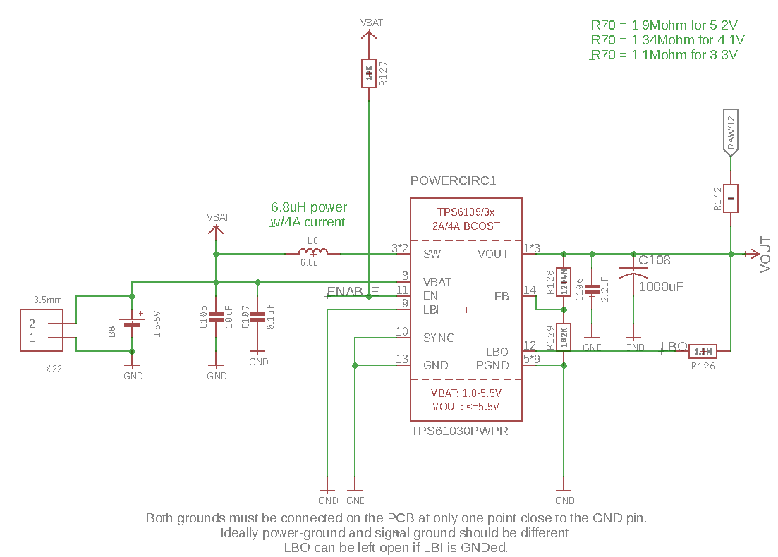
I used the TPS61030 for powering a simple smart metering device, boosting a 3.6V

lithiumThionyl chloride spiral-battery to a constant 3.7 V to power a SIM800C

communication module.

For pilot testing, I deployed 10 smart meters on the same day and ran it on accelerated

transmission mode (to see how long the batteries last). On the 16th day all of the smart

meters stopped transmitting simultaneously. When I inspected the pilot batch (3 samples)

I found that not only were the batteries completely discharged (as expected) but even

the tps61030 chips were short circuited internally.

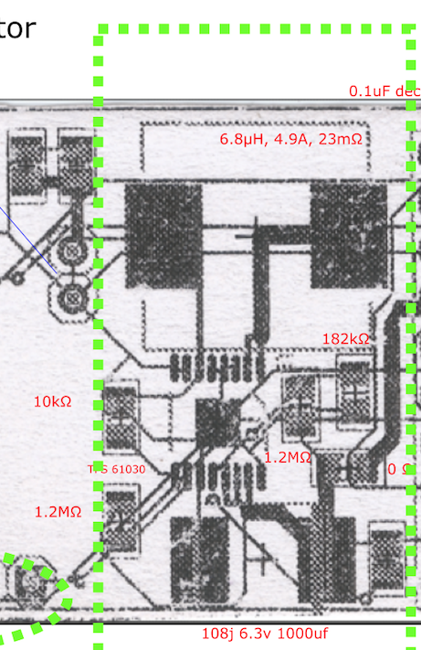
I've not been able to figure out why this could've happened. I've tried to follow the layout

guidelines by TI but have put a beefed up tantalum capacitor at the output (1000pF instead of

the 100pF).

Have attached a section of the schematic below. Hoping if TI could throw some light on what

may have happened.

  • Does the SW pin of TPS61030 short to GND? if yes, the device should be damaged by bad layout. could you share your image of the layout?

    for your application, i would suggest TPS61021a, which is simple to use and smaller solution size.
  • Hey Jasper

    Unfortunately I do not have access to the actual softcopy of the

    layout file right now but I do have a high res scanned hard copy.

    I hope you will be able to see the traces clearly.

    The 2 top left tracers are the SW pins and I don't think they are shorted to GND. 

    You wont be able to see the polygon layers for VBAT, VOUT and GND but they

    exist.

    Also, about the TPS61021a, I need to give a 4V output and supply 2A pulse current

    requirement. Will it be suitable?

    Can you also suggest a dual power solution so that I can supply a constant 3.3V to

    the microcontroller and 4V to the sim module simultaneously with a 3.6V LiSOCl2

    battery as source?

    Rgds

    Karan 


  • Just to give you a better perspective. Actual and layout side by side

  • 1. about the TPS61021A, it can't support continued 4V 2A. but in your application, the 2A should be pulsed current, which can support through aluminum capacitor. as in this reference design "www.ti.com/.../TIDA-01387"

    2. The TPS61030 layout is bad, which causes the damage of the IC. please follow the suggestion in datasheet and this application note to modify the layout "www.ti.com/.../slva773.pdf"
  • Hey Jasper

    Thanks for the info. The second link is very helpful.

    However, w.r.t TIDA-01387, you had provided me a resolution a few months

    here. I see 2 problems with this solution:

    1. The supercaps in the design are not available in the suggested form-factor and

    to get a custom solution with multiple caps in parallel is not only costly but also takes too 

    much space.

    2. If I opt for a variant of  LiSOCl2 batteries  which come with the attached 1550 super caps,

    that too is a costlier option overall. More than that I wish to ask you if going for super-caps

    will be less efficient power wise because the capacitors will have a high self-discharge?

    Can I also request you to please guide to me a dual power solution where I can simultaneously

    power my microcontroller at 3.3v and then use the micrcontroller to switch ON/Off the power regulator

    to provide 4V to my GSM module?

  • 1. the main purpose of the reference is to show the capability of the TPS61021A. you don't need to follow all the circuit. you can select a lisocl2 battery and the HLC or other solution to replace the super capacitor.
    2. about the dual power solution, no sure if the device like TPS610981 is OK. which bypass the battery voltage when it higher than 3.3V.
  • Hey Jasper

    between tps61021A, tps61230. tps61236 which would you

    recommend for this application>

    Rgds

    Karan

  • you can't select TPS61236P because this device requires VOUT at least 0.6V higher than VOUT
    TPS61230 is GOOD if it's input voltage is acceptable. or TPS61230A is better, only with the concern of input voltage range.
    TPS61021 have wide input voltage range, but its current capability is smaller.
    i would suggest TPS61230.