A related question is a question created from another question. When the related question is created, it will be automatically linked to the original question.
If you have a related question, please click the "Ask a related question" button in the top right corner. The newly created question will be automatically linked to this question.
yes, connecting the ADJ/GND pin to GND is correct for the TLV1117 with fixed output voltage.
I see two issues:
1. The TLV1117 needs an output cap with an ESR between 0.2R and 10R to work stably. This is easiest achieved with an aluminium electrolytic. The ESR of a ceramic cap might be too small.
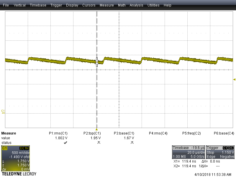
2. I think the input ripple form the DC/DC-switcher is punching through the TLV1117 because of insufficient power supply rejection ratio (PSRR) of TLV1117 at the high switching frequency. So, I would recommend the introduce of a filter between the LMZ12002 and the TLV1117. Put a 10...22µH high current choke in front of the input cap of TLV1117. If you notice ringing add some series resistance to the choke.
Even a simple high current ferrite bead could be sufficient as filter.