Part Number: TPS549B22
Hi Expert,
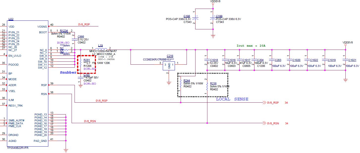
Please see our schematic as below(Figure1).
The remote sense(RSP/RSN) has been separated two locations.
The near-end sense location connection by R238 and R244 to output capacitors.
R238 and R244 only connected when initial verification DC-DC converter.
We let R238 and R244 OPEN circuit in the system application.
The far-end remote sense pins connection with ASIC(BCM56873) pins as an illustration(Figure2).
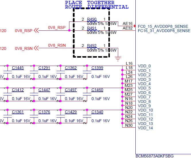
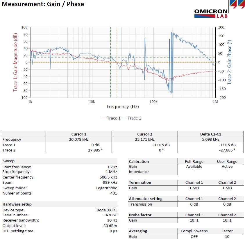
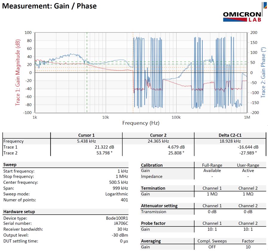
We replaced 0ohm with 10ohm at R490 and make R491 open circuit for bode plot measurement.
The result shows unstable as an illustration(Attached1).
Then we check power rail filter design, there have ferrite beads between DC-DC output capacitors and ASIC decoupling capacitors(Figure3).
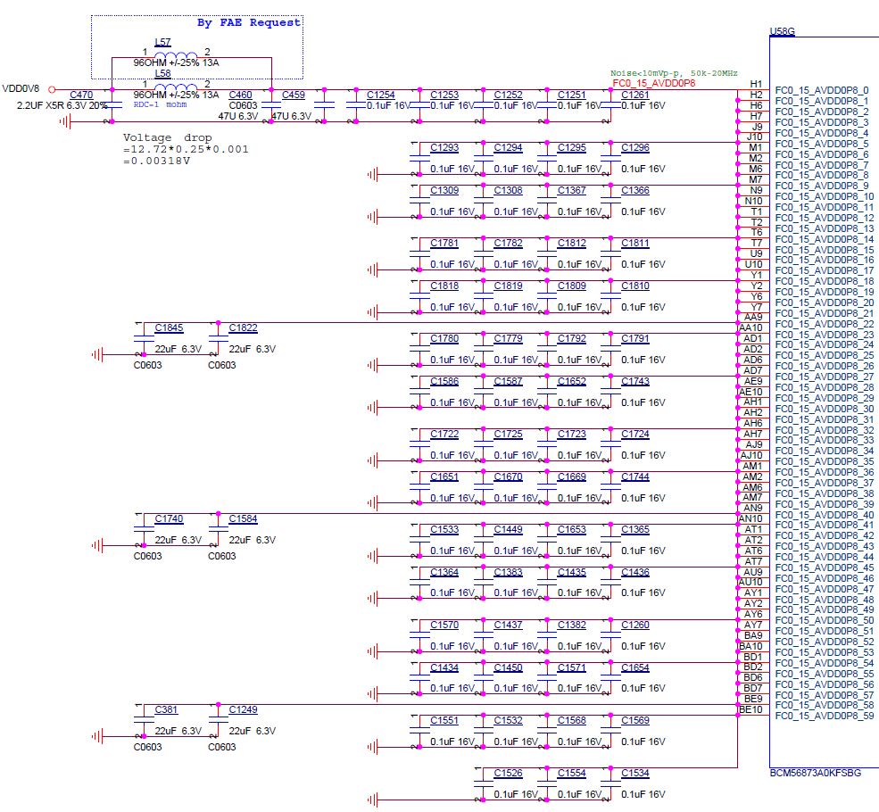
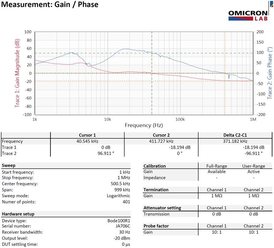
It seems to me, the ferrite bead and decoupling capacitors will create another Pole in DC-DC converter. That makes converter unstable. However, we remove the ferrite bead(let this two pad short circuit.) and measure bode plot again. The result shows stable(Attached2).
The problem is our customer would like following Broadcom chip suggestion puts the remote sense location at the chip pins and using ferrite beads for noise immunity. But, that will cause DC-DC converter unstable.
Do you have any suggestion to improve the design? Should I add any compensation networks?
Look forward your feedback. Thank you.