This thread has been locked.

If you have a related question, please click the "Ask a related question" button in the top right corner. The newly created question will be automatically linked to this question.

LM2842XMK-ADJEV: Component destroy after 1 to 5 power on.

Part Number: LM2842XMK-ADJEV
Other Parts Discussed in Thread: LM2842

Hello,

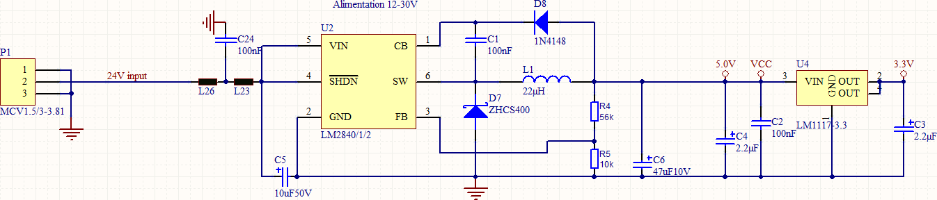
We use LM2842 since few years without problem but on a new range of product the LM2842 systematically be destroy after few power-on :

We have 24V input, 5V output to power a Cortex M4 MPU + 4.3 inch LCD display (about 200/250mA under 5V).

The pre-production batch was working since few month without problem. Now we make a first production batch of 300 boards and LM2842 stop working one after one.

We add a soft start on pin4 and it seems to correct the problem. 

I would like to understand why the LM2842 is destroy now ? 

Thanks for your help,

Sebastien

  • Hello Sebastien,
    This is very unusual, that device suddenly breaks after working for months.
    Has anything changed between pre-production board and boards sued in production?

    Looking at your schematic if you are using LM2842, which is 600mA device, your diode might be insufficient to handle inrush current during startup. The diode shown on the schematic is rated for 400mA and inrush current during startup might be higher. This could potentially explain why behavior is better when you add filter on shutdown pin, enabling device in more controlled manner.
    To verify if this is the case please try following:
    1. use diode rated for slightly higher current (for example 800mA), such as MA2YD26 (recommended in datasheet) or PMEG6010CEH
    2. increase value for C1=220nF

    If none of these helps, provide your board schematic and layout for further review.
    Regards
    Brani
  • Hello Brani,

    thanks for your quick reply. I've ordered new diodes for testing (both reference are difficult  to find actually, I find this one with similar characteristic and same footprint than ZHCS400 : BSR106WS-TPMMSTR from Digikey.

    I will receive them Friday.

    Here the PCB around the LM2842 for information :

    Regards,

    Sebastien

  • Hello Sebastien,
    After looking at the layout above i think the issue observed may be caused by less than optimal layout.
    Following comments:
    1. No input capacitor is visible . Proper placement of input capacitor (as close as possible to the IC pins 5&2) is absolutely essential. This device will experience large discontinuous currents on input and if input bypass capacitor is placed far way from the device it will negatively affect device behavior/performance. So placing small input bypass capacitor 100nF between pins 2&5 is very important for proper operation.
    2. bootstrap capacitor C1 is not visible on your layout, meaning it is very far from device itself. C1 should be placed directly between pins 1&6 (between diode D7 and IC is enough room to place C1).
    3. PCB trace that connects pin 6 to the diode D7 and inductor L1 is very thin. This trace needs to carry output current and from visual observation looks like it is insufficiently thick to do that. Suggest 2x or 3x of current trace thickness .
    4. Suggest removing thin traces that connect ground side of D7 to ground and use solid copper fill for this connection.
    5. suggest adding more ground vias.

    For refernce please refer to suggested layout on page 16 of device datasheet.
    www.ti.com/.../lm2842.pdf

    Regards
    Brani
  • Hello Sebastien,
    Since there was no activity on this thread for past week i will go ahead and close it.
    regards
    Brani
  • Hello Brani,

    Thank you for your reply.
    I will modify my PCB and components values in this direction.

    Best regards,
    Sebastien