Other Parts Discussed in Thread: TPS61170, TINA-TI
Hello!
I've calculated component values for example circuits from LM2735 documentation to check the design equations before designing my converter.
8.2.12 LM2735X WSON SEPIC Design Example 12
(1.6 MHz): VIN = 2.7 V - 5 V, VOUT = 3.3 V at 500 mA
Let's use T = 25C, Switch resistance = 0.19 Ohm, current = 3A,
"A good design practice is to design the inductor to produce 10% to 30% ripple of maximum load." - p.16, LM2735 doc.
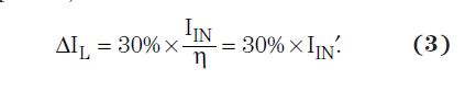
"A rule of thumb is to use 20 to 40% of the input current," - slyt309.pdf
Let's try the range of inductor ripple: 6% to 33% of Iswitch.
vout = Vout + Vdiode = 3.3V + 0.5V = 3.8V
Vin.max = 5V - Vswitch = 5V - 3A * 0.19 Ohm = 4.43V
DCmin = vout / (vin.max + vout) = 3.8 / (4.43V + 3.8V) = 0.462
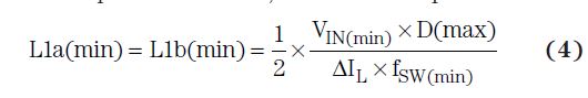
Lmin = vin.max * DCmin / (Fosc * 0.33 * Isw) = 4.43V * 0.462 / (1.6MHz * 0.33 * 3A) = 1.3uH
Lmax = vin.max * DCmin / (Fosc * 0.06 * Isw) = 4.43V * 0.462 / (1.6MHz * 0.06 * 3A) = 7.1uH
Vin.min = 2.7V - Vswitch = 2.7V - 3A * 0.19 Ohm = 2.13V
DCmax = vout / (Vin.min + vout) = 3.8 / (2.13V + 3.8V) = 0.641
Lmin = Vin.min * DCmax / (Fosc * 0.33 * Isw) = 2.13V * 0.641 / (1.6MHz * 0.33 * 3A) = 0.86uH
Lmax = Vin.min * DCmax / (Fosc * 0.06 * Isw) = 2.13V * 0.641 / (1.6MHz * 0.06 * 3A) = 4.74uH
As result: 1.3uH < L < 4.74uH
The example circuit uses 6.8uH.
If I use "10% to 30% ripple of maximum load" (from 0.1 to 0.3 of 0.5A) than the result is 7.8 uH < L < 28.44uH
So the circuit inductor value 6.8uH is also out of the range.
What's wrong with the calculation?