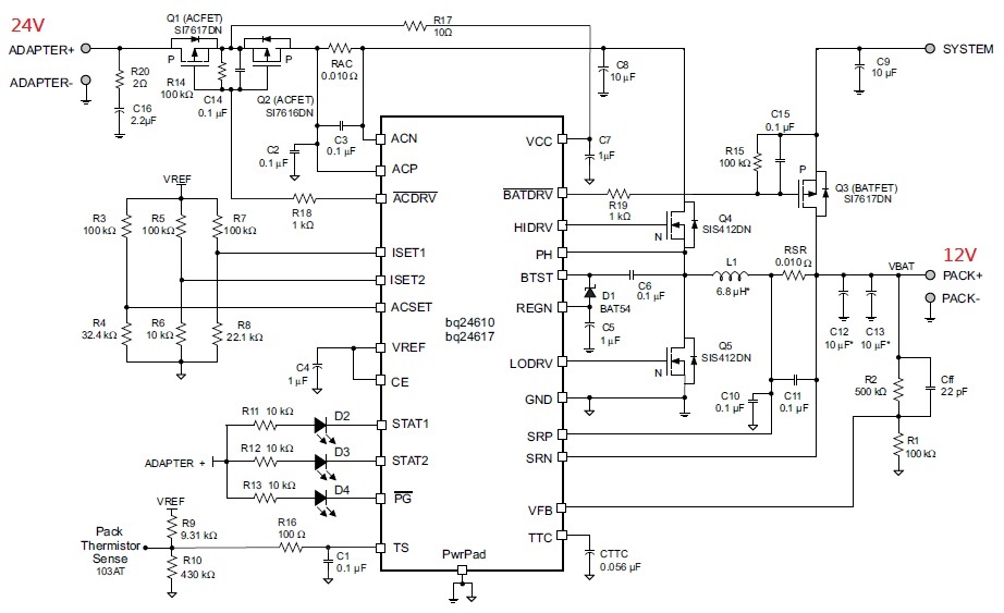
Dear experts, please refer to below figure. Because my system only can be supplied from battery(The voltage can not be exceeded 13V), so I modified the schematic. The Q3 MOS does not be connected to extrenal DC Adapter. Does this design be OK?
This thread has been locked.
If you have a related question, please click the "Ask a related question" button in the top right corner. The newly created question will be automatically linked to this question.
Dear experts, please refer to below figure. Because my system only can be supplied from battery(The voltage can not be exceeded 13V), so I modified the schematic. The Q3 MOS does not be connected to extrenal DC Adapter. Does this design be OK?
We recommend to connect the drain of Q3 between L1 and RSR such that the sense resistor can sense the charge current.
With the connection in your schematic, the sense resistor senses the sum of the load current and the charge current. The charger will not have control over the charge current. Your termination will be affected.
Yes. In the case where input is absent, there is no converter output current for the device to sense.