


Hello,
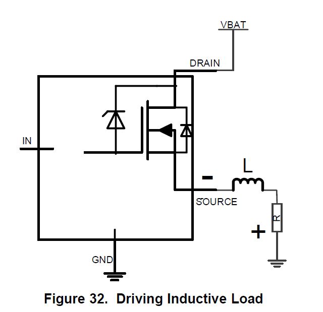
Can you please let me know how internal clamp diode connected to drain to gate is helping to clamp negative OUT pin voltage during inductive load turn off? I am not able to figure out complete path for inductive energy dissipation
.
Hello,
Can you please let me know how internal clamp diode connected to drain to gate is helping to clamp negative OUT pin voltage during inductive load turn off? I am not able to figure out complete path for inductive energy dissipation
.
