


Other Parts Discussed in Thread: BQ76920, BQSTUDIO, BQ24617
BQ78350-R1
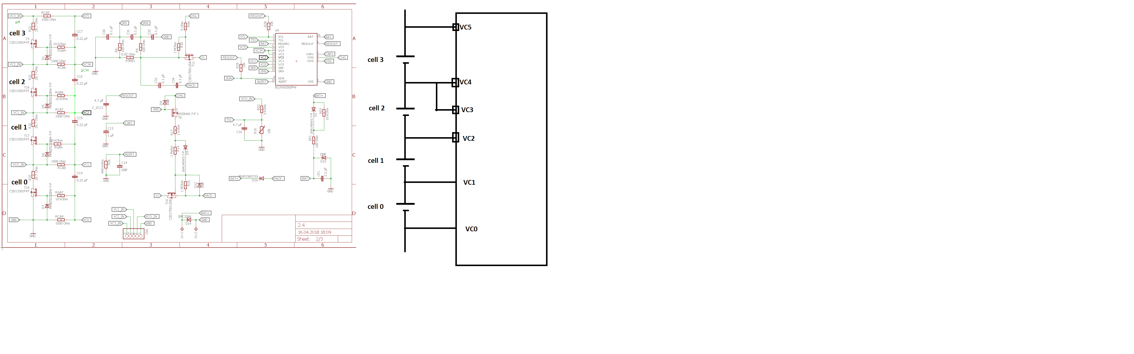
1. issue: My Batterymanagmentsystem can work with 4 cells. The BQ76920 can work with 5 cells. As described in the datasheet of the BQ76920 on page 46 I have to short pin VC4 and VC3, if I want to work with 4 cells.
But now in the AFE Cell Map Register, which I can see in BQStudio, there is only CELL_5, CELL_2 and CELL_1 in onstate. Normally I would expect that CELL_4 would also be in onstate.
So I tried to change the state of CELL_4 from 0 to 1. But than BQStudio is loosing connection with the BQ78350-R1 and I cant get connection anymore?
Was it correct to connect VC4 and VC3 together?
What can I do now? Must I replace the BQ78350-R1?
BQ24617
2. issue: When Im charging the battery I should see that the Pin STAT1 should be HIGH and STAT2 should be LOW?
In my case its the other way arround. In my case STAT1 is LOW and STAT2 is HIGH, while im charging?
What could be the problem here?
3. issue: The Batterymanagmentsystem is connected with BQstudio. Imt trying to calibrate the voltage and the current. It is said that I have to have at least 1 A flowing through the load.
What kind of load are you using to simulate these current? Obviously I cant use resistors because the maximum power dissipation of resistors is to low.
4.
2. issue: I have a problem with the charge current. I decided to choose a RSR-Resistor with a value 0.05 Ohm. This should give me a charge current of 2 A.
Because: I_charge=Viset1/(20*RSR) => 1/(I_charge*20)*Viset1=RSR => RSR=1/(2*20)*2=
But my system is only charging with 120 mA.
I measure the maximum voltage of 2 Volts at ISET1 and ISET2.
Which reasons could there be, that restrict the charge current.

