This thread has been locked.

If you have a related question, please click the "Ask a related question" button in the top right corner. The newly created question will be automatically linked to this question.

BQ24170: 5V Application Circuit Schematic

Part Number: BQ24170

Hello,

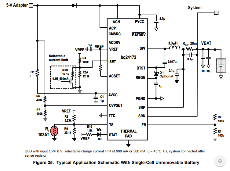
I am working on a system utilizing the BQ24170 in 1-cell configuration. While looking at the datasheet, I saw this example application circuit for a single-cell, nonremovable battery and a 5V charging adapter. This appears to be exactly what I need.

However, this circuit is missing numerous MOSFETs and the charger current sense resistor that the other application circuits show. Is this 5V example circuit in error, or can I copy and use this schematic without any problems?

Thanks in advance.

  • Hi,

    You can use this circuit, there are no problems with it, although it does come with some assumptions of your application.

    Since there is no use of power path (meaning that charging current will reduce to supply system connected at PVCC), then the input current limit is not needed. The maximum power that the charger will need from the adapter will be: Max power = VBATREG*(ICHG+ISYSAVG)/Efficiency.

    The input FET (ACDRV) are replaced by the diode, and the battery FET (BATDRV) is removed because the system will power directly from the battery when in battery only mode.

    Set your charging current limit (ISET) such that the current being delivered is higher than your charging current plus the system average current.

    Regards,
    Steven