This thread has been locked.

If you have a related question, please click the "Ask a related question" button in the top right corner. The newly created question will be automatically linked to this question.

LM338: Protection diode from the adjustment terminal to the output

Part Number: LM338

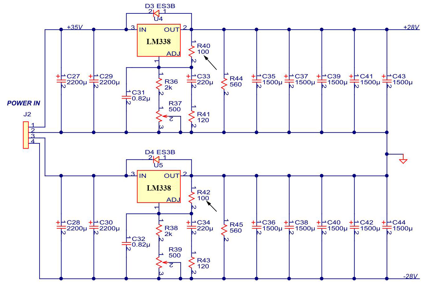
Does the LM338 require a protection diode between the ADJUST pin and the OUTPUT pin to prevent die overstress (in parallel with R40 and R42)? The output voltages is 28 V and 0.82µF capacitance in parallel with RC-circuit (120 Ohm and 220µF).

  • Hi Alex,

    your design is a bit unusual. Why do you have inserted R41 and R43? It will take much of the advantage of C33 and C34. And why do you have so much output capacitance?

    I would add protection diodes across R40 and R42, although they probably might not be needed because of the current limiting provided by resistors R41 and R43.

    And I would think about adding reverse voltage protection diodes at the outputs of supply (antiparallel to C43 and C44).

    Kai
  • Hi Alex,

    According to the datasheet, if you have output voltage > 25 V or ADJ pin cap > 10 uF you will need a protection diode from ADJ to OUT as shown in Fig 18 of the datasheet. What is the purpose of R41 and R43?

    Why do you have so much input and output capacitance?
    Cin = 4400 uF
    Cout = 7500 uF

    What voltages do you have on pins 3 and 4 of the J2 connector? Is there a reason why you are not using a negative linear regulator for U5?
  • It's PSU for audio amplifier. J2: U21=35V, U34=-35V. We are not using a negative linear regulator for U5 due to the absence of a suitable (Vin=35-36V, Vout=28V, Iout=5A). 

    According to the datasheet no protection is needed for output voltages of 25-V or less AND 10-µF capacitance. But you said if we have output voltage > 25 V OR ADJ pin cap > 10 uF you will need a protection diode from ADJ to OUT as shown in Fig 18 of the datasheet. 

    That's why I wanted to understand whether a diode is needed when two conditions are fulfilled simultaneously (Vout=28V and ADJ pin cap > 10 uF) or if at least one of the conditions is fulfilled (Vout=28V or ADJ pin cap > 10 uF), then a diode is needed.

    LT338 we used earlier does not need any protection diodes between the adjustment pin and the output to prevent die over-stress. 

    The C31(C32)=0.82µF capacitor in parallel with R41C33(R43C34)-circuit (120 Ohm and 220µF) affect the output impedance of the regulators. The values are chosen in such a way as to minimize output impedance in a wide frequency band (up to 100-200 kHz).  Cout = 7500 uF + linear regulator on LT338 = impedance (resistance and inductance) is determined by the trace already. According to my calculations, in my 4 layer layout only 1oz of copper will be 2.5mOhm from 0 to 100-200kHz. Output capacitance  7500 uF used to improve transient response and stability

  • Hi Alex,

    You will need protection diodes from ADJ to OUT. When Vin or Vout go to 0 V, the charge in the ADJ cap will need a path to conduct to ground. If there is no protection diode, the lowest impedance path is through the ADJ pin which can damage the LM338.

    The amount of charge is related to both the capacitance and the voltage across the capacitor. Q = C x V. I should have written that a protection diode is required if either the output voltage > 25 V or ADJ pin cap > 10 uF or both.