This thread has been locked.

If you have a related question, please click the "Ask a related question" button in the top right corner. The newly created question will be automatically linked to this question.

LM5116: LM5116 Evaluation Board

Part Number: LM5116
Other Parts Discussed in Thread: LM5119

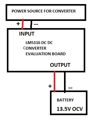
I am testing LM5116 Evaluation Board for its performance and functionality to verify if it satisfies our requirement. The test which I conducted was to connect a battery in parallel with the output of the evaluation board. But there seems to be a drop in the output voltage from required 12V to around 10V when a battery with OCV 13.5V was connected. Kindly provide suggestions to rectify the problem. A demonstrative circuit for the same has been shown below. 

  • Hello Ansurhree,

    It is likely that start up into a pre-bias load may be having an issue with Gate Drive supply of the HSF. I would try decreasing Cboot from 1uF to 100nF. 100nF should be more than adequate.

    Hope this helps?

    David.
  • Hello David,

    Thanks for your reply. I shall work out this and let know the results.

    I also have another doubt, while upgrading the design for 20A load. If suppose i use a SMD type MOSFET, will the heat dissipation be affected? WIll the MOSFET perform well in case i use it for automobile applications that runs for so many hours with worse environmental conditions. Please provide me suggestions if SMD would be OK to proceed or should i switch to Discrete type for 20A loads at the output end.

    Anushree

  • I would suggest you implement a dual phase controller for a 200W design. You can consider the LM5119 as device that can be configured as a dual phase design having 10A per phase. This will help control Temp rise of the power components. If you still opt to use a single phase, you will need to use a heat sink or air flow. for calculating the power dissipation in the FETs, please refer to the link below.


    www.ti.com/.../slyt664.pdf


    Hope this helps?

    David.