This thread has been locked.

If you have a related question, please click the "Ask a related question" button in the top right corner. The newly created question will be automatically linked to this question.

BQ24192: Doubts about waveforms

Part Number: BQ24192
Other Parts Discussed in Thread: BQ24190,

Hello guys,

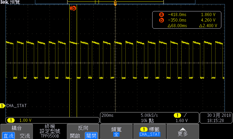
I have a question with the "BQ24192EVM" Board. The following waveform was my measurement at Pin 4 STAT. According to Spec, when any fault Digital condition occurs, STAT pin in bq24190, bq24192 blinks at 1 Hz,but the measured frequency didn't match. Is this normal design for the bq24192? 

  • Hello User,

    This is not what would be expected for this waveform. Can you give me more information about your setup? Specifically:
    1. Is your pull up set to VBUS or VSYS?
    2. Is there a battery or source meter connected to BAT?
    3. What is your fault condition that you are testing?

    Thanks,
    John
  • Hello John,

    1. The voltage high is VBUS.
    2. This is not included loading and battery.
    3. I want to test the STAT action when charge IC hasn't any loading, becasuse the action is reference for my programming.

    Thanks
  • Hi User,

    I was able to recreate a 12 Hz waveform similar to what you are seeing. The STAT pin is high when charge is disabled/complete and low when charge is enabled.

    In this case, the capacitors by the BAT pin are charged up to the Charge Voltage Limit. When charging the STAT pin is low. Once VBAT reaches this full charge limit, the charge is disabled and the STAT pin goes high. The capacitors on BAT dissipate charge and VBAT drops. Once VBAT goes to under the Battery Recharge Threshold, the charge is enabled again and the STAT pin goes low. For the default capacitors that are on the EVM, this cycle occurs at 12Hz.

    The only difference between our waveforms is that the STAT pin alternated between about 3V and 0V in my measurement. It looks like the STAT pin has a DC offset in your measurement. My measurement is on TP10 (STAT) can you confirm where you are measuring from?

    Thanks,
    John
  • Hello John,

    I ask questions in another way. In the Spec, the description of STAT pin is "when any fault Digital condition occurs, STAT pin in bq24190, bq24192 blinks at 1 Hz". My focus in on the "1Hz". Why is the peak and trough time of my measured waveform not commensurate and is not as 1Hz in the description?
  • Hi User,

    With no battery the STAT pin will have a square wave at 12Hz with no faults. In my testing, I forced a thermal fault by shorting J6. After doing this the STAT pin square wave changed to 12Hz. In your testing, which fault condition are you trying to trigger?

    As for the amplitude of the signal, a square wave of about 2.5V is expected. From the pull up rail, there is a series resistor and diode that will cause a voltage drop, which is why the STAT pin is at that amplitude.

    Thanks,
    John