This thread has been locked.

If you have a related question, please click the "Ask a related question" button in the top right corner. The newly created question will be automatically linked to this question.

LM5160: LM5160 Immediately Blowing Up At Power On

Part Number: LM5160

Hello:

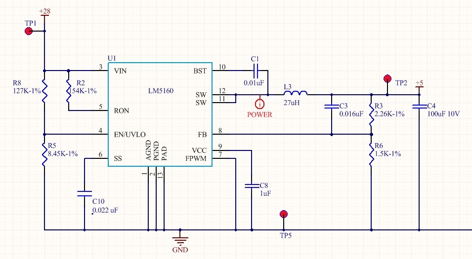
We used the Webbench design tool to make a design for the LM5160. It should take +28v and convert it to +5v

Upon first power up, with no load, we have destroyed all five of boards with the LM5160. The part turned on, regulated to +5v for about 4-6 seconds, and then the input current spiked to about 0.8amps at +28v and the part smoked. I've checked the reference design, web-bench, all the parts on our board, the pinouts, the layout, and rebuilt the design in the TI-TINA tool. Everything says the design should work, yet the part is failing immediately.

What could be causing this? Please help

  • Hello Steven,


    Does the device fail when you lower Vin? Do you have an input capacitor for your design (not shown in schematic)? Is this placed very close to the IC? Is there an input filter also? Is the filter damped?

    Even with no input filter, using long cables can ringing and over shoot of the input voltage. for input damping you can use a bulk Electrolytic with relatively high ESR, say 100's of mR? The bulk electrolytic will need to be much larger than the input ceramic capacitor.

    What is the ISAT level of L3? Is Isat>Ilim max of the LM5160 (2.875A)? You can measure the inductor current at start up, this would be helpful?


    What is the ESR of C4, are you sure its adequate to ensure stability? Please refer to the Datasheet, for Type II ripple injection, making sure you have satisfied the requirements? This can easily happen if you paid attention of cout capacitors while ignoring the suggested ESR?

    I would get a scope and monitor Vin on power up, if you do not see any overshoot on Vin.

    Please make sure you have laid out as per guidelines in the datasheet

    If you have checked off all of above, then it likely there is a error on the board that is differing from your posted schematic?

    Hope this helps?

    David.
  • Maybe it's the 27uh?the reference  design has 47uh. According to the manual calculations, 26uh is the minimum value allowed.

  • I just saw your reply. There is a ball capacitor Elsewhere on the board. I've checked esr of caps and they're all good grade Ceramics so they should be fine. What's frustrating is I have one board, before it died, that was regulating at 5 volts for several seconds. Then some event occurs and the part is damaged. I'm wondering if it has something to do with that inductor throwing a spike or dumping too much current back into the switch pin. It's almost like a buck regulator if you forgot the schottky protection diode. This part being synchronous should work though without the schottky. I only have two other switching Regulators on this board and they're also working just fine. This lm5160 is the primary regulator though the power everything else Downstream.
  • And to add more frustration. We overnighted parts from digikey and FedEx point in Memphis. So we didn't have any testing today because we don't have any party hopefully they will come tomorrow and we can revisit this. Very strange. I have a switching regulator in probably a decade. I've designed dozens of them they've all works just fine. Certainly not smoke in 5 seconds
  • Hello Steven,

    sorry for any confusion, I am refering to the ISAT level of the inductor, this needs to be greater than 2.875A, if not, you may run into a reliability issue?

    Hopep this helps?

    David
  • Hello Steven,

    I am referring to the ESR of electrolytics to provide input filter damping. the ESR needs to be high to provide adequate damping. Cermaics have very low ESR. Please note, you still need the ceramic capacitor and this needs to be located close to the device as outlined in the datasheet.

    David.
  • Hello Steven,

    Can I take a look at your layout? Thanks.

    David.
  • It's 4.2 amp Isat inductor. The bulk cap is about 4.4uF ceramic 100v, almost exactly what's on the reference design. And it's failing at no load, so we shouldn't be anywhere near saturation. Really strange.
  • Hello Steven,

    This rules out Isat of inductor being the cause of your issue. On a side note, at no load, you still will have high current at start up as energy is supplied to charge up Cout.

    Regarding Cout, what is its ESR?

    Thanks.

    David.
  • Hi

    Its about 0.08 to 0.1 ohms, its a 100uf 10v X5R cap in a 1210 package.

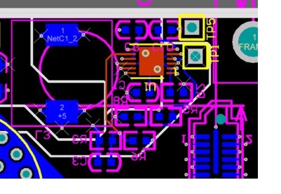
    The layout is attached here, its in an area about 0.75 inches by 0.3 inches, its pretty compact on a 6-layer board. The SW pins are into planes and all +28v input are on full planes with full ground planes.

    One thing, in checking all of the part#s, I noticed we are using the LM5160 and not the LM5160A.

    That shouldn't matter? Is there some difference between the 5160 and 5160A (besides the VCC pin allowing external drive) that we should know?

  • Hello Steven,

    I am assuming pin 1 (Gnd) is in the bottom Right hand side of the device in the layout pic you posted?

    Unfortunately it appears that the layout guidelines have not been followed? The layout guidelines are presented in the datasheet on page 27.   The biggest issue I see is you do not have Cin close to the device.  I did not see an input cap on the schematic you posted either?  this need to be next to the pins Vin and Gnd...

    It should be noted that CVCC, Cboot and feedback network all need to be placed close to the device.

    I believe your issue is directly related to the layout?

    Hope this helps?

    David.

  • i don't know about that. the input cap is a little further away, so that isn't actually right next to the part. we are going to add one right next to it at the two test points. However, I can't believe the part would explode in 5 seconds with no load. I am going to add another 2.2uf closer to the component - which is easy to do.
    Again though, the part turned on - regulated to +5v volts for several seconds and then it fails. So it acheived steady state, got beyond the ramp up to power the COUT, and then self destructed. This makes zero sense
  • And all of the other parts are within 0.200" inches of the LM5610. You can't really get much closer than that. Even on the reference design, they are about 0.100 to 0.150 away. The parts take up space. If the feedback network was 6 inches away with 3 mill traces...sure that would oscillator. 1/10th of an inch away on a 6-layer board, with no load ... and seeing the part regulate to +5v... something else isn't right?
  • Hello Steven,

    I am sorry, I don't mean to labor the points here...but I believe the following needs to be addressed in addition to Cin.

    1. C1 need to be close to the pins

    See datasheet suggestion below.

    "CVCC and CBST: The VCC and bootstrap (BST) bypass capacitors supply switching currents to the high and

    low-side gate drivers. These two capacitors must also be placed as close to the IC as possible, and the

    connecting trace length and loop area must be minimized (see Figure 36)."

    2. Feedback network is far from the feedback node

    See datasheet suggestion below.

    "The feedback trace carries the output voltage information and a small ripple component that is necessary for

    proper operation of both the LM5160 and the LM5160A. Therefore, take care while routing the feedback trace

    to avoid coupling any noise into this pin. In particular, the feedback trace must be short and not run close to magnetic components, or parallel to any other switching trace."

    Hope this helps?

    David.

  • Well see... I think the issue is related to inductor and spikes somehow. Interestingly, I can't get webbench to recommend 27uh.. Only 47uh now. I have new parts and inductors coming tomorrow. We will figure out the issue here.
  • Ok - its fixed now. So you were on the right track with the Cin capacitance. Even though ours is about 0.350" inches away from the LM5610, it should have worked. BUT! The pcb was built with a 0.01uF cap and not the 2.2uF bulk input caps. So the board really didn't have any CIN at all, just 0.02uF. The inductance of the leads from the power supply, combined with the incorrect CIN was causing a huge ground bounce. When the inductor started up, the SW would see about -15V on it due to ground bouncing and it would cook the chip. Replacing the 0.01uf with the 2.2uF, its working just fine now.

    What a hassle. Thanks for forum replies