This thread has been locked.

If you have a related question, please click the "Ask a related question" button in the top right corner. The newly created question will be automatically linked to this question.

BQ76930EVM: Frequent Freezing

Part Number: BQ76930EVM
Other Parts Discussed in Thread: BQ76930, BQ78350-R1,

Hi,

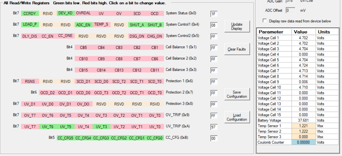
I have been working with the BQ76930 EVM for a few days and I currently am frequently experiencing an issue when the module is scanning. After following the setup instructions to connect the module to my computer I begin scanning with the bq769X0 Evaluation Software and usually within about 10 seconds the GUI stops receiving new data from the module. This usually requires a hard reset of the board and the GUI in order to begin receiving data from the EVM again. Has anyone else experienced this issue and/or are there any tips to fix it?

Thanks!

  • Hi Connor ,
    Thank you for your interest in our products. A BMS expert has been assigned to your question.

    Regards,
    David
  • Hi Connor,
    When used with the gauge the situation you describe is common for voltage based shutdown. A common cause is an incorrect setting of the AFE Cell Map so that the gauge reads a near 0 voltage on a cell which is not connected and shuts down from under voltage. See section 6.4 of the EVM user guide on correcting this issue. www.ti.com/.../slvu925b.pdf
    Another possibility since you mention the bq769x0 Evaluation Software scanning and since the EVM allows connection of both the bq78350-R1 and the external interface to the I2C lines is bus collision between the gauge and scanning interface. The gauge can see an incorrect voltage due to the bus collision and shut down the AFE. Be sure you have the shunts removed to the gauge, see figure 1 of the EVM user guide.
  • Hi,

    Thank you for the recommendations. I am currently not using the gauge, and I have removed all 4 gauge shunts. Can the gauge still shut down the module if I do not have the gauge shunts connected? Based on your description of what would happen if the gauge was connected, that seems to closely align with the problem I am seeing where I can read the cell voltages only a few times before the voltages stop changing on the GUI.

    Based on your other advice, I have not yet removed the resistors as recommended by section 6.4, but I have shorted C3 to C4 and C8 to C9 (giving me an 8-cell based configuration). After doing this, I still seem to be having the issue when applying 38V.

    I also noticed that once this issue has occurred, the GUI sometimes has the System Control 1 register momentarily flash 00, then FF, and then almost all of the registers turn red. Could that be happening if the BQ76930 is off? See the image below for most of the registers turning red.

    This all happens very quickly, in <1s. I am not sure why this  is occurring?

    Thanks again for your fast response,

    Connor

  • Hi Connor,
    Removing the shunts to the gauge is the correct approach, and if removed the gauge can not shut down the module.
    It seems you must be losing power or connection to the board somehow. You may need to inspect the signals with an oscilloscope. Check for loose, contaminated or damaged contacts on the 4 wire cable to the interface. Check that the supply is not current limiting and dropping the voltage to the board.
  • Hi,

    Apologies for the slow response. -- OK, I have an oscilloscope connected from GND to VC10X (since I have the 10 cell version and VC10X supplies BATT). Upon applying ~38V with a Kepco Power Supply, my oscilloscope appears to read 38V across the two pins. My power supply has been set to current limit at 250 mA, which is much greater than what the BQ76930EVM should be drawing.

    Any other ideas?

    Thanks!

    Connor

  • After some more testing, I believe I understand why the voltages stop changing --
    Upon some observation, while running the byte 0x04 (System Control 1) is originally 10 and then without any user input changes to 08 or 0C [(0001 0000) ADC is on] to [(0000 1xxx) ADC is off]. This appears to only occur when I have checked the "Scan" button (for scanning automatically). I was able to manually "Update Display" about 50 times and had no issues.

    I have not yet seen anything in the documentation to indicate that this is a normal function. Has anyone else reported the issue?
  • Hi Connor,
    It sounds like you are on your way to identifying the problem. No it does not sound familiar or expected.
    Reading all FF for registers is common if there is a broken data line, but it usually happens after the slave nacks the address. There should be a status message in the bottom of the window or a popup window if the device nacks. It is hard to envision how a series of reads from the device by scan would cause a write of 0x08 to register 0x04.
    You might look for some disruption on the group power supply VC5X, the internal supply CAP1, or the REGOUT supply.
    Your supply setting seems OK, but you might increase your current limit on the supply to see if it works better.
  • Hi,

    Unfortunately, the oscilloscope did not capture any dips in VC10X, VC5X, CAP1, or REGOUT. I increased the current limit, but the issue is still occurring. I wondered if it was possible that Reads and Writes through the I2C were getting jumbled so I delayed the scan time as much as by 5 s between scans and the issue still occurred.

    I may be able to get away with just using the "Update Display" button for most of the tests I am doing, so I may just go with that.

    Thanks,

    Connor