


Other Parts Discussed in Thread: BQ34Z100
Dear Sir, Madam,
My customer has the enquiry below.
1) The LEDs for P1 and P2 are required for capacity indication. Can the FETs be removed and LEDs direct connected to the pin? Any issue?
2) Any way to trigger the LEDs blinking to indicate battery capacity? Is it possible to have 2 alternative control input to trigger the LEDs blinking, for example 1 is from battery pack and 1 is from the end device?
Below is Maxim DS2788 which my customer using previously, there is a pin called "PIO" for the function, for your reference.
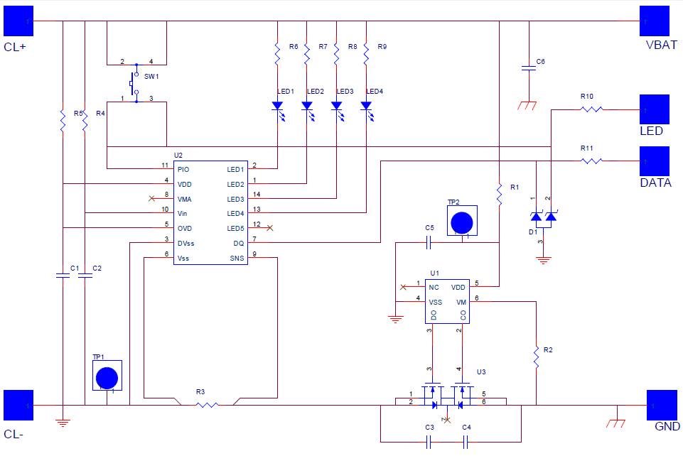
My customer using a FET as a switch, when there is a pull high from device, it will turn on the FET then REG25 will give 2.5V to VEN pin and LED light will display to show battery capacity.
This FET is in parallel to the push button switch for the LED display.
Does the design need an extra protection component if switch and FET are in parallel.
For the current limiting, a limiting resistors and a blocking diode are added.
Hope to hear from you soon. Thanks.
