This thread has been locked.

If you have a related question, please click the "Ask a related question" button in the top right corner. The newly created question will be automatically linked to this question.

BQ76940EVM: BQ96740EVM board testing

Part Number: BQ76940EVM
Other Parts Discussed in Thread: BQ76940, BQ78350

Hi,

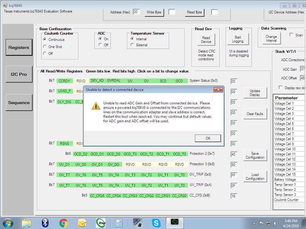
We have tested the BQ76940EVM board with using TI eval software and we found below issue while testing.

 -------

Our lithium ion battery pack specification: 10S1P(42V 2600mAh) each cell max voltage is 4.2V @2600mAh and evaluation board has been configured for 10S cells as per the BQ76940 datasheet.

Input power supply:bench power supply aplab ld3205 (stetted voltage to 42V, current max )

Connected load:Rheostat 42E (1A) connected at Pack-,Pack+

We are communicating with the only BQ76940 and not with BQ78350 gauge IC,related I2C gauge shunts has been removed & board is connected with the PC through I2C using  EV2300.

--------

kindly find my queries below.

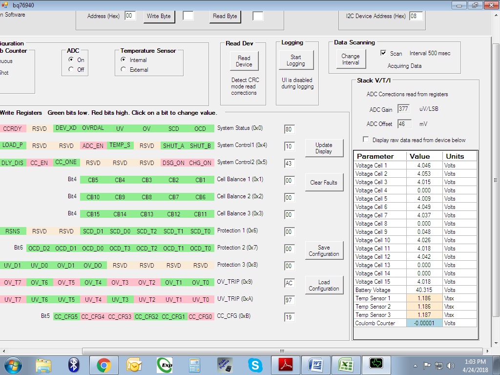
1) We have observed that cell no1 voltage is showing 3.66V or still below 3.66V in TI GUI and the cell voltage is 4.0V if we measure the cell voltage individually with millimeter.(screen shot has been attached) why it is like that?

2)If we enable the DSG_ON & CHG_ON through TI GUI then the load is drawing current from the power supply and not from battery pack.

3)Power supply is used for battery charging purpose or for board supply?

3)Battery not getting charged  and cell balancing also not happening.

4)I didn't understand the coulomb counter readings in TI GUI.please explain.

as i know coulomb counter is measures the accumulated energy added to and removed from a battery, allowing accurate estimates of battery charge level.

5)What is temperature sensor internal and external? internal means die temperature of IC? and external means  readings from the external 3 thermistor ?


Thank You,

Awaiting for your valuable reply.

Regards,

Rajaneesh

  • Hi Rajaneesh,
    A BMS expert has been assigned to your question.
  • Hi Rajaneesh,
    If evaluating with a power supply connect like figure 1 of the EVM user guide. Short the appropriate cell inputs at the terminal blocks to simulate your desired cells.
    If connecting cells, the top and bottom of the battery stack connect to BATT+ and BATT- of the board, and each cell tap connects to the appropriate terminal block terminal including the top and bottom of the stack. Cell 15 and BATT+ must be connected together outside the board. Similarly Cell 0 and BATT- must be connected outside the board. The resistor divider should not be used as it will drain the cells.
    1. Something is not connected properly. Use the meter to find where the voltage is lost and connect properly. If the proper voltage is present on VC1 with respect to VC0, and VSS is connected to the same voltage as VC0, the device must be damaged.
    2. There should be no power supply used with cells unless it is to charge the battery.
    3. Check connections. Battery charge would come from the PACK terminals if the FETs are enabled. Cell balancing would be controlled manually by the operator. The bq76940 does not automatically balance cells. If the cell balance registers are set to non-zero values the part will continue to balance until the cells are depleted. The controller must decide when to balance.
    4. The coulomb counter reading represents the voltage across the sense resistor during the preceeding 250ms interval. It is an integrated value.
    5. Yes, internal is die temperature and external is from the thermistor. Note these are voltage readings and must be converted to temperature by the controller.
  • Hi,

    BQ76940EVM board is not able to communicate with I2C,Error screen shot has been attached.What would be the problem?

    few minute before i worked with the same board ,same setup & same PC,it was working fine.after few sec i found that issue.related screen shot has been attached.

  • Hi Rananeesh,
    Since the board was running possibilities may be:
    I2C address changed in the window unintentionally
    Wire came loose for power or communication
    Pull up shunt came loose if using EV2300
    Short of some signal on the board cutting off the power or damaging the part