This thread has been locked.

If you have a related question, please click the "Ask a related question" button in the top right corner. The newly created question will be automatically linked to this question.

TPS22810: request Ids spec

Part Number: TPS22810

Dear TI,

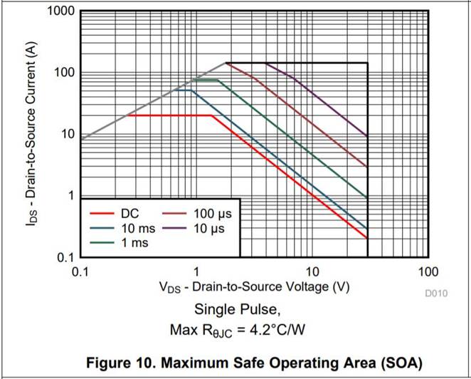
If there is a graph of Ids according to the voltage of the TI's load switch TPS22810DBVR, please share for us.
It seems that it is not in the datasheet which was downloaded from TI webpage.

The application is an ON-OFF control load switch for the + 12V fan power supply (DC) and should have sufficient Ids value at + 12V DC.

thanks,

TS

  • Hi TS,

    We do not generate these SOA curves for our load switch devices. In general, the TPS22810 can handle 3A DC. Do you need higher current than that? If so, what peak current do you need and for how long of a pulse?

    Thanks,

    Alek Kaknevicius

  • The power specifications are as follows.
    + 12VDC input/output, and maximum 1.5A continuous condition.

    thanks,
    TS
  • Hi TS,

    Is this fan being controlled by PWMing the TPS22810? If the TPS22810 is just being turned on to provide 12V/1.5A DC to the fan, then this will be no problem. How are you managing the inductive kickback across the TPS22810 when the fan is switched off?

    Thanks,

    Alek Kaknevicius

  • Hi Alek,

    I have some questions.

    1) What does inductive kicking back mean?

    2) Please check the following circuit below. The applicable schametic is as follows. (12V_FAN1: Max 1.5A, 12V_FAN2: Max 1.5A each)

    3) Which part should be modified when adding 12Vin PWM in the schematic below?

    thanks,

    TS

  • Hi TS,

    1) Inductive kickback is when an inductive load is turned on/off. During this time, the current across the inductor is changing, so this creates voltage spikes (V = -L dI/dt). Depending on the inductance of the load and the design of the circuitry, this could result in high positive peaks and low negative peaks. These voltage spikes need to fall within the min/max specs for the output of the TPS22810 to guarantee no damage in the design. I mention all of this because sometimes fans are inductive loads, so I want to make sure the device is safe in the design.

    2) The devices look good, I don't see any problems in the schematic.

    3) I am not sure how the fans are being controlled because I do not know the specifications for driving them. Maybe a PWM signal is required, but these may also only need a DC supply. Based on the CT capacitor chosen, it does not look like the plan is to PWM the output through the ON pin.

    Thanks,

    Alek Kaknevicius