Dear TI:
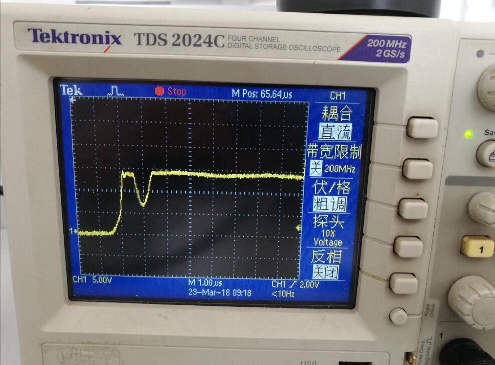
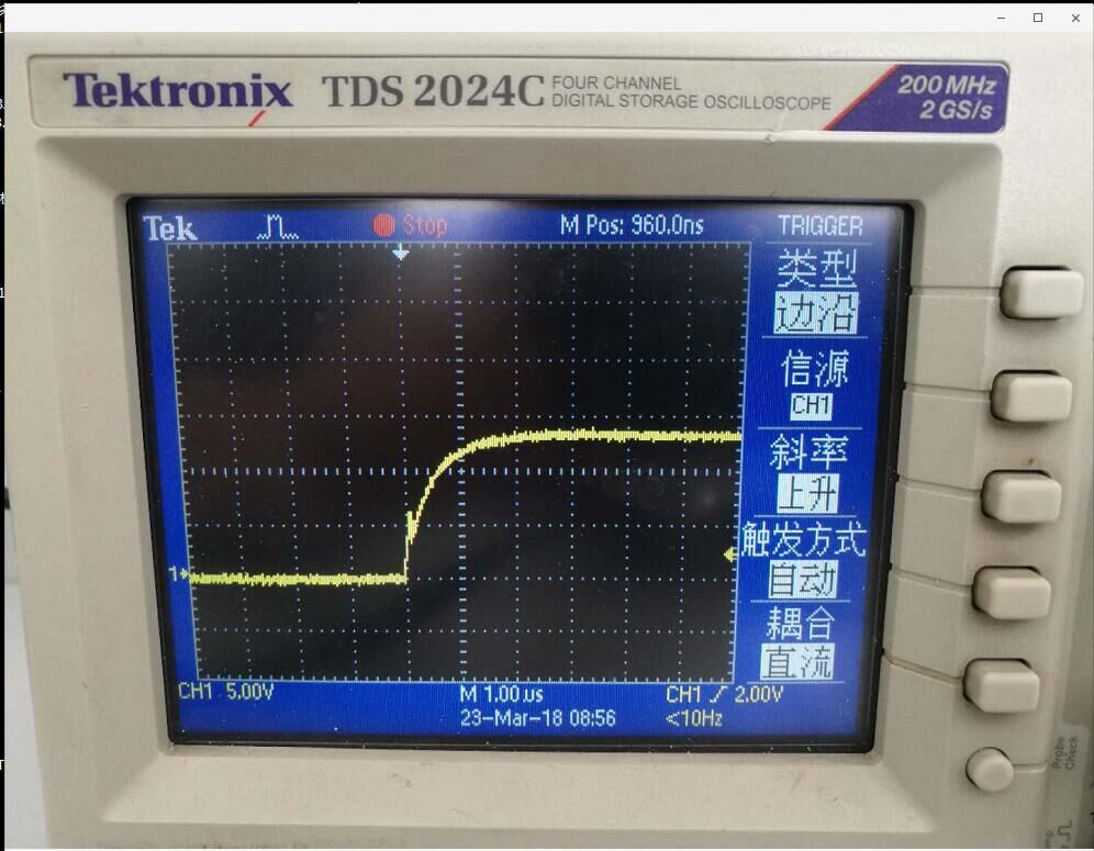
Customer use UCC27531 instand of discrete components to Driver MOS(IRF1404S/L). But G_MOS Waveform was bad, i was a liitle confused
fsw=20KHZ ,ID=40A, VDD=12V.
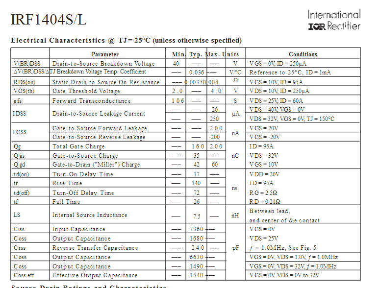
MOS Parameter:
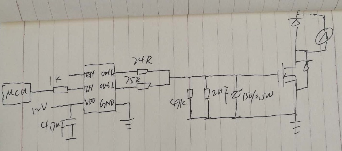
Schematic:
Dear TI:
Customer use UCC27531 instand of discrete components to Driver MOS(IRF1404S/L). But G_MOS Waveform was bad, i was a liitle confused
fsw=20KHZ ,ID=40A, VDD=12V.
MOS Parameter:
Schematic: