This thread has been locked.

If you have a related question, please click the "Ask a related question" button in the top right corner. The newly created question will be automatically linked to this question.

UCC28180: External current limiting

Part Number: UCC28180

Hi,

I am using the UCC28180 for a 100V 3.5kW PFC converter with LLC. The application is audio amplifier. For continuous sinusoidal amplifier output of up to 3.5kW I have no problem with the controller and its operation.

However, when we apply burst mode tests  where 2-4 cycles at 500Hz with powers greater than 8kW is applied followed by a continuous sine at a much lower level, the input current rises significantly higher causing the FETs to fail. Using the SOC and PCL control within the IC seems useless as the ICOMP saturates resulting in a high current spike on top of the sinus waveform, which causes failure of the device too. This seems to be a known problem having read on the forums, so I have set the limits much higher so it doesnt interfere.

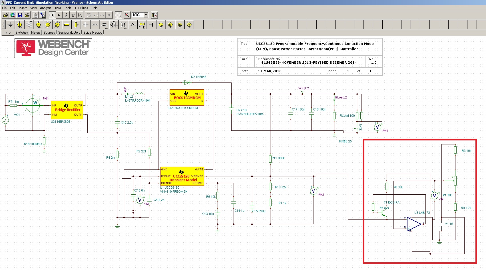
I am looking to implement a current limiting circuit externally where the I disable the PFC by shorting the Vsense when the current is higher than a set limit causing the output voltage to drop and enables once the current reduces below a threshold.

I am looking for some input into any circuits which have been used previously to perform this function. Alternatively, your opinions on whether or not this is a feasible solution would be very helpful.

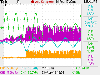
In the image below CH4 is the output signal of the amplifier, CH2: is the PFC input current, CH3 is the resonant converter current. At present I am using the current limiter on the resonant converter, but it doesnt seem to be the best solution as it affects continuous power operation.

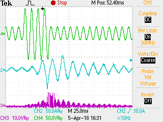
Without current limiting of the resonant converter the input current looks as below.

Thanks

Pravin

  • Hi Pravin,

    Normally the overcurrent protection and behaviour is determined by the dc/dc isolation stage and not the PFC stage.

    It sounds like you need an external comparator on the current sense (CS) signal that is independent of the UCC28180 protections. It should be possible to breadboard the circuit and test it on your existing design.

    Pulling Vsense below 0.82V will put the PFC controller into standby mode and it will restart in Soft Start mode, which is good.

    This is the first time I have seen such a big discrepancy between the nominal full load power, 3.5kW and the transient load 8kW, as I said earlier normally this issue is managed by the dc/dc stage.

    Regards

    Peter
  • Hi Peter, Many thanks for getting back to me. I am attempting to try this current limiting at a lower power level. When the trip occurs, the current drops to the lower hysteresis threshold and the current ramps back up to a high level again causing an overshoot in the output voltage. My suspicion is the VCOMP does not fully discharge through the internal discharge path within this time period, thus there is no soft-start.

    I was thinking of applying the circuit directly across the VCOMP capacitor to rapidly discharge it and put it into a soft-start state as opposed shorting the Vsense resistor. Do you think its a good idea?

    Thanks,

    Pravin
  • Hi Pravin,

    You are probably correct as the VCOMP feedback network is slow, low bandwidth, and you may get better performance managing the VCOMP voltage directly.

    I also think its a good idea to try this at low powers!

    Regards

    Peter

  • Hi Pravin,

    Since there is no activity on this post I will close this thread and if you have new questions please start a new post.

    Regards

    Peter
  • Hi Peter,

    I managed to find a workable solution to my problem.

    The method involves measuring the Vsense voltage and clamping it to a set Vsense voltage during heavy loading on the falling edge. Please see image below.

    This tricks the controller into thinking that the voltage  at Vsense has not dropped below a programmed reference voltage as it flat lines whereas in reality, the output voltage continues to sag, which is acceptable for the application. The current demand during the dynamic loading conditions is thus limited.

    The closer the programmed reference voltage is to 5V target , the tighter the limit to the input current. The reference voltage is set low enough so as not not current limit during continous 3.5kW  operation and only comes into effect when loading dynamically.

    Thank you for your input so far. The outcomes of various current limiting methods finally led to this solution, which means that the current waveform is able to maintain its sinusoidal profile when limiting instead off chopping off the PWM operation.

    Best regards,

    Pravin