This thread has been locked.

If you have a related question, please click the "Ask a related question" button in the top right corner. The newly created question will be automatically linked to this question.

LM5176: Output Issue

Part Number: LM5176

Hello All,

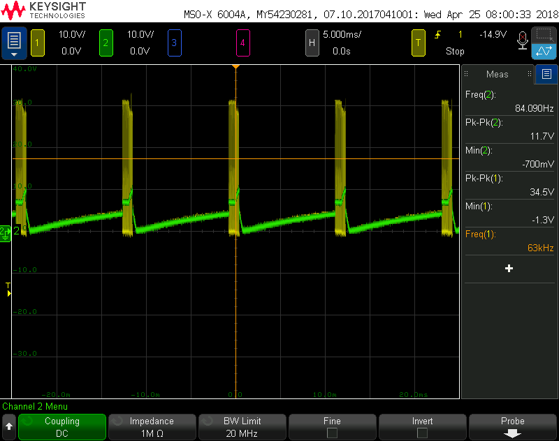
I'm currently working on a design which implements the LM5176 for an input range of 9-50V, an output of 24V, a max load current of 1A and a switching frequency of 300kHz.  Unfortunately, we've had some issues with the output.  

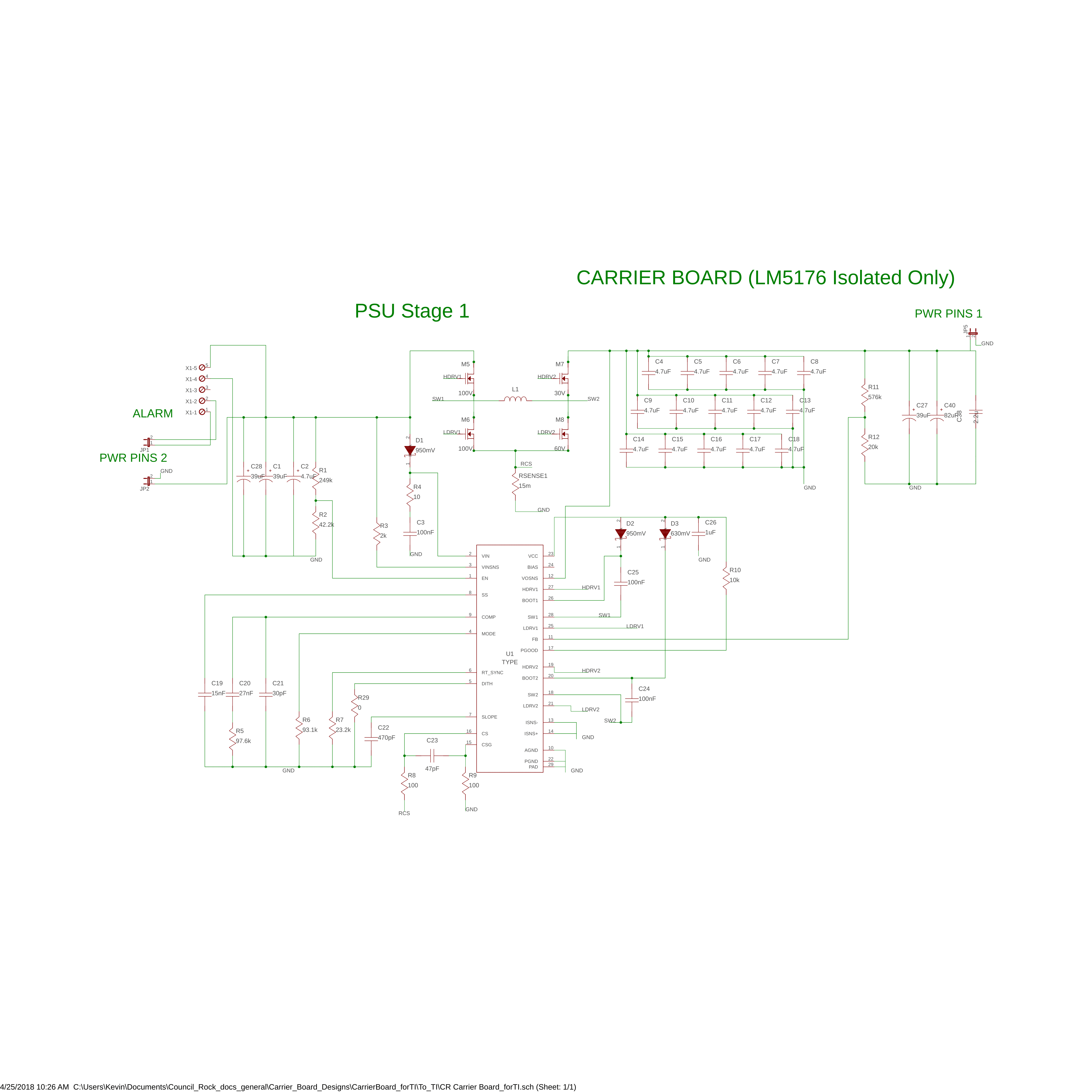
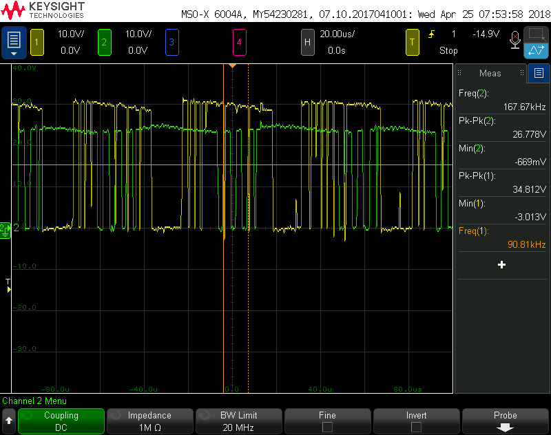
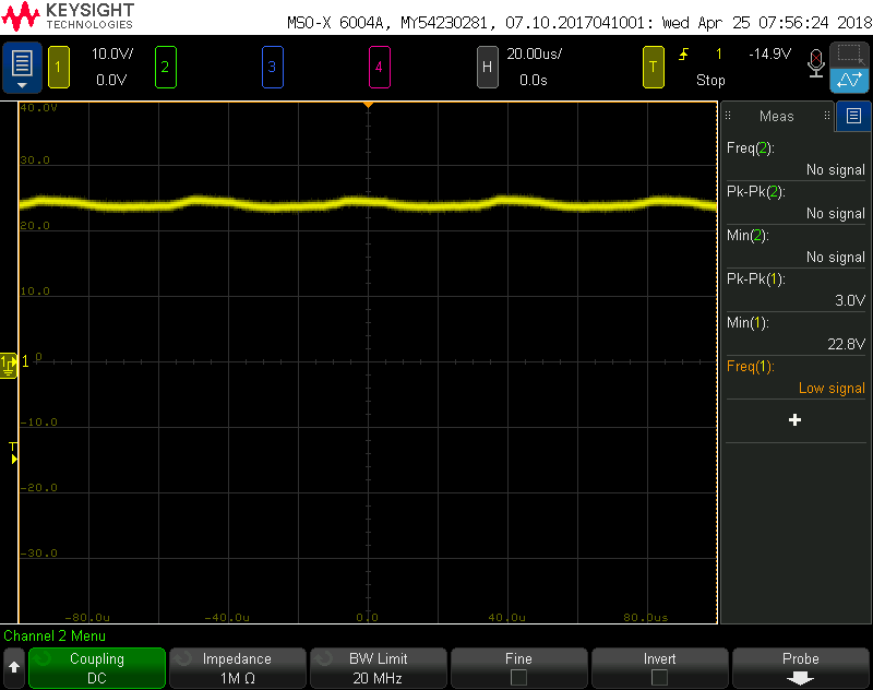
In boost mode (12V input) with no load we do see an output of 24V.  However, the current pull jumps between 0.2A and 0.5A and the inductor makes a very audible whine.  As time increases, the frequency of this pitch as well as the current pull increases.  The inductor also gets quite hot.

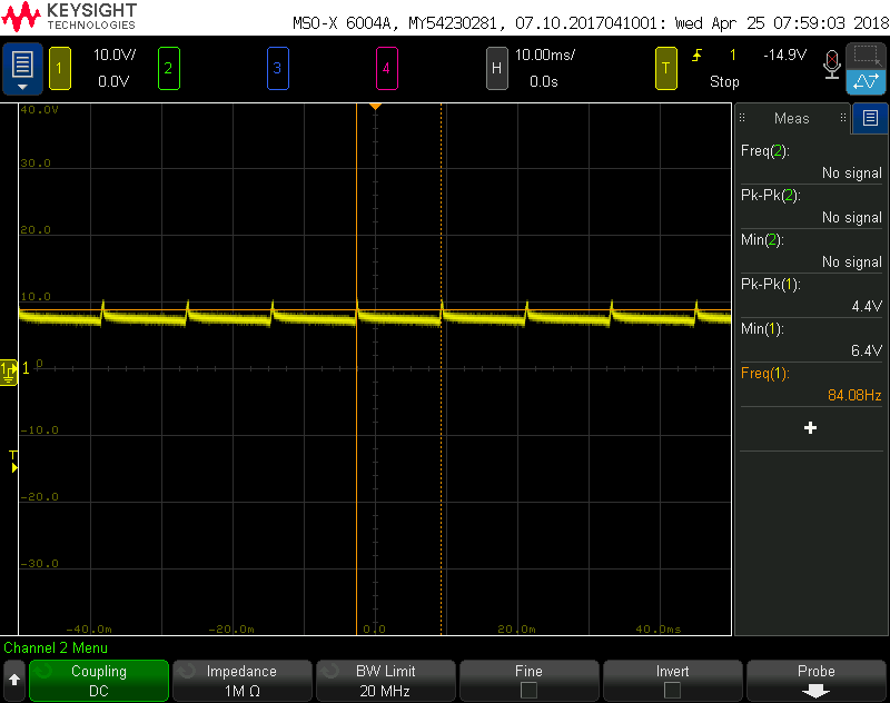
When attaching a load of around 0.3A, the output voltage drops to 6.5V but the inductor no longer heats up quickly and the current pull is stable.

The design was made using the WEBENCH tool and we've checked most of the math using the LM5176 datasheet.  Is there anything that stands out about the issues we are experiencing?  I can provide waveforms, schematic, list of materials, etc. as necessary.

Thank you for the help,

-Kevin Gates

  • This can be an result layout issues, or loop compensation issue. Please send your schematic, and also show waveforms of SW1 and SW2 when the problem shows up.
  • Hi Youhao,

    Thank you for the quick response!  I've included all the relevant info I can think of bellow. The design I'm currently working with is a special version of our board where we only populated the LM5176 and surrounding circuitry to attempt to fix our issues with it.  I can also provide our board layout and bill of materials, but not in an open forum.

    Thank you for the help,

    -Kevin

    Schematic:

    Boost (12V Input) No Load - TOP SW1 (Yellow) SW2 (Green), BOTTOM Vout (Yellow):

    Boost (12V Input) 112mA Load - TOP SW1 (Yellow) SW2 (Green), BOTTOM Vout (Yellow):

    Buck (30V Input) No Load - TOP SW1 (Yellow) SW2 (Green), BOTTOM Vout (Yellow):

    Buck (30V Input) 112mA Load - TOP SW1 (Yellow) SW2 (Green), BOTTOM Vout (Yellow):

  • Re-studied your circuit. You schematic is not very clear because the junction dots are missing at a few places, so I am not sure if the connection is correct or not.

    Anyway, the circuit is obviously unstable. Please use the LM5176 buck-boost quick start design tool, and calculate the compensation values. The tool can be find at the following link: www.ti.com/.../snvc208
  • The missing dots seem to be some issue with eagle (I cannot place them at those wire intersections). However, the connections are present. I've verified this by creating a netlist and looking through it.

    We were eventually able to solve our issues by reviewing the LM5176 datasheet design example. Our Schematic had an improper value for Rsense that overloaded the inductor L1. In addition, the values for the circuit off the COMP pin had to be modified.

    Thank you for your responses and the time you put into this issue,
    -Kevin