This thread has been locked.

If you have a related question, please click the "Ask a related question" button in the top right corner. The newly created question will be automatically linked to this question.

UCC27714: HS has phantom jump to HO

Guru 55913 points
Part Number: UCC27714
Other Parts Discussed in Thread: UCC2895, , TIDA-00778

How possible is it that UCC HO/LO Totem poles reversed design require inverted PWM on HI/LI?

We used same application firmware with top gate driver over past years and not had such PWM issues as with UCC. We can not get UCC B phase PWM to transition onto either side or back to phase A or C phase.  The B phase LI seems to disrupt HS/HB discharge of Cboot path and drive inverter voltage very high above DC supply stopped  by MCU over voltage faults.

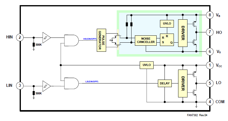
Notice the HO/LO PFET is reversed on other vendors gate driver!

  • Hello,

    Please double-check your circuit. We have many other customers using this device without issues. I suspect something in your particular implementation is causing the issue.
  • Hi Don,

    That really doesn't answer my question of why both Totem poles FETS are reversed from other vendors driver or if the HI/LI expect inverted PWM signals in that aspect?

    It seems the LO output is not always producing pulses that the HO output (CH2) always indicates a presence of a falling edge input to LI. Setting scope to capture the LO Ton rising pulses is very random to capture them on CH2 making it seem as if HI/LI inputs are reversed yet they are not. And it still does not answer how Cboot discharge cycle is somehow being compromised by LO. There is no slope in the Cboot discharge on HS output. Perhaps this IC is simply defective then if inverted PWM was not expected on HI/LI.

    I'd bet a tall stack of chips other vendors gate drivers work properly in the presence of non inverted PWM signals where all 3 UCC drivers are failing to function on any level!

  • Several other points of light:

    Are you guys assuming other customers are using non-inverted MCU driven PWM signals?
    Perhaps other customers simply used the UCC2895 PWM generator with inverted PWM drive signals to HI/LI?

    Figure 38 would be more believable if drawn (Q') driving both Totem poles so HI/LI did not require inverted PWM drive signals?

    Has TI ever bothered to bench test UCC27714 against other manufactures gate drivers under the exact same PWM conditions before making the claim top of datasheet "Best-In-Class" on several key points? How could TI simply assume from signal timing that the gate driver could replace other manufactures "Best-In-Class" gate driver claims?
  • It would seem the UCC27714 gate driver requires complementary input signals HI/LI to function properly. No where in UCC27714 datasheet has any such fact been elaborated or expressed or otherwise noted by figures of signal diagrams. Fact is timing diagram Figure 1/39 both appear to express typical PWM generated signals MCU are capable to produce, nothing about complementary drive signals here.

    TIDA-00778 Engineer perhaps skirted behavior by leveraging Piccolo DSP to generate Sinusoidal wave forms driving UCC27714 (HI/LI) inputs. Yet another engineer who simply failed to acknowledge the UCC27714 had major difference to other manufactures gate drivers thus boasting similar Marketing points above that of the completion.

    Perhaps it may require either HO or LO be inverted to make the UCC27714 believe either HI or LI are receiving complementary input signals. Such as the UCC2895 Figure 14 indicates being produced, however (after the fact) of common knowledge being expressed in UCC27714 datasheet disclosure.

  • Hi BP101,

    The logic inputs are shown in Table 3 of the data sheet.  The only limitations are UVLO which may get tripped if the bootstrap gets discharged, or if the ENable is low. I wonder if the issue isn't UVLO getting tripped?

  • Seemingly the evidence points to table 3 being complete nonsense if the HI/LI inputs are not kept complementary at any point of PWM operation.

    How else could Q be losing control of HO to the point any PWM pulse width sent to HI/LI during Cboot charging >2us causes MCU POR events. Or any PWM pulse width that exceed 2us driving Cboot charging the DC voltage at times peaks over 90vdc from 24vdc  supply. Often LI pulses can not be captured by scope yet cause HS to drop a pulse on HO apparently via high side NFET drain B+ rail.

    Something is seriously wrong with these three gate drivers, produce same sick wave forms in capture. Suspect for one Cboot is not fully charged and the pulse width is set very low to avoid MCU POR events. The UCC27714 seemingly can not handle copartner half bridging where only one of either part of the half bridge (HI/LI) receives a PWM drive signal as the other input remains low. Let alone claiming best in class when HI/LI has been restricted to >100 pulses may have a lot to do with HO jumping to B+ rail in below capture.

  • Don Dapkus said:
    The only limitations are UVLO which may get tripped if the bootstrap gets discharged, or if the ENable is low. I wonder if the issue isn't UVLO getting tripped?

    Had suspected the same weeks ago but Cboot on HS/HO pins have a 0v potential prior to Cboot charging and HS/HO 13.6v to GND. Also if UVLO was tripped how could PWM wave form be produced even sick as it appears in above capture?

    Perhaps have TIDA-00778 engineer test a trapezoidal DSP wave shape on Piccolo MCU from the very same design guide we followed for gate drivers on our PCB layout. The only difference is COM pin 5 is connected directly to AGND versus the top of low side NFET shunts. 

  • Hi BP101,

    Very odd, indeed!

    For your scope shot, what is the ground reference for your HO channel (ch 1)?

    Where is Ch 2 connected?
  • Hi BP101,

    Normally, you would only want one switch on at a time to prevent shoot-thru the bridge. But, we don't have any protection in this IC, so if you command both HI and LI high, both HO and LO should go high.

    I doubt this is the issue, but worth mentioning. Please read section 8.2.2.9 LO and HO Overshoot and Undershoot of the d/s. This can cause erratic triggering on the UCC27714.
  • I was reefing to the complementary signals as outlined in UCC2895 Figure 14.

    The problem is the UCC27714 HO/LO pulse width is not following HI/LI drive pulse signals <100ns or >2us pulses without causing Cboot to act like an uncontrolled voltage generator. Trying to charge Cboot via LO side causes HO to jump to rail and sends spikes into B+. Even not charging Cboot via LO there is so much PWM trash from Cboot being thrown onto B+ via HS through high side NFET's. Perhaps a proper Cboot RC time constant as datasheet formula suggest roughly 0.12uf yet TIDA-00778 engineer opted for 1uf to compensate for unknowns. We currently use 1uf Cboot with other gate driver and have not issue with overshooting. So it remains questionable how TI would release UCC design having such odd behavior without making internal corrections before doing any mass production runs. It seems another project killer is slow decay near 1% duty cycle high NFETS can not be achieved via the UCC >100ns pulse restriction. UCC datasheet also claims 0-100% duty can be achieved but chokes badly on 500ns LO pulse width and drives 80v-90v B+ spikes in the process. The UCC HO charge pump is not behaving properly, for what ever reasons acts like a high voltage generator even with 200ns LO/HO pulses.

    Oddly skipping initial Cboot charge cycle produces better wave forms but the HO pulse width remains uncontrollable above 2us in first 2500us of PWM drive. We have dynamic dead band delay controlled via software checking for HI side drive of previous PWM cycles. That appends dead time onto the LO side via MCU delay generators after an HI falling edge has been detected in the 3 generators output control register. Thusly enables or disables DB generators control feature for the specific1/2 bridge in output cycles. Doing such stops shoot through and is fully proven with other gate driver. Had actually designed for FAN73901, last minute decide on UCC after seeing 4 amp IC gate driver from TI with seemingly excellent control features.   

    Don Dapkus said:
    . Please read section 8.2.2.9 LO and HO Overshoot and Undershoot of the d/s. This can cause erratic triggering on the UCC27714

    How could overshoot of HO occur in the first few cycles of PWM unless the pulse width is far to wide. Sounds a bit crazy as typical overshoot occurs at high voltages where (dv/dt) is occurring on HS input. If UCC Schmidt triggers are so sensitive how they work so well at 300vdc in TIDA-00778 with basically the same hardware configuration. IGBT's have NFET front end just as prone to overshooting. So it seems to me the Charge pump is highly suspect in this issue more than anything else.

  • BTW: I was wrong about the pulses on left side of capture CH1 being Cboot charge pules. They are actually a few cycles of a single code fired after 5ms Cboot pulses far left. So that single code occurring after Cboot drives HO to B+ as if Cboot is lost or being charged when HO then attempts to drive the NFET when it should not. And LO is driving pulse CH2 which made me think it was a Cboot charge cycle but that is the sign wave shape far left
     
    It almost appears the UCC is self priming Cboot charge from LO side NFET body diode and does not require charging.

  • Hi Don,

    Don Dapkus said:
    Normally, you would only want one switch on at a time to prevent shoot-thru the bridge. But, we don't have any protection in this IC, so if you command both HI and LI high, both HO and LO should go high.

    Wouldn't you know it was lack of dead band low side B causing middle phase overshoots during the transition of Cboot charging HO. Oddly causes under voltage conditions more often if DB code was set to check each PWM cycle all 3 UCC without LO #2 UCC checks. That was a tip off something was different from other vendors gate driver behavior, far as anyone can tell there is no protection either in their driver but 100-300ns Ton propagation delay, Tr times 20-140ns. UCC#1,  UUC#3 were often not being effected as UUC#2 was every time.

    That said voltage overshoot HS jumps to HO might be due to UCC shorter delay HI to LI (center) phase requires both sides of 1/2 bridge be dead band protected. Now have random times of overshoot UCC#2 but magnitude is not what it was prior, startup code gets a lot farther,  HS now has turn off slope Cboot returning to a float level each cycle. So it seems the HO Totem pole was being over biased by CBoot not being fully discharged each PWM cycle leading to HO overshoot.  

    Thank you for giving direction on this crazy issue!

  • Hi BP101,

    I'm happy to hear you are making progress on getting your system up and running! I know how frustrating this can be sometimes.
  • Yea but not the kind of progress we desire as the story untangles into a new dimension.