This thread has been locked.

If you have a related question, please click the "Ask a related question" button in the top right corner. The newly created question will be automatically linked to this question.

TPS62065: ILIM Thermal Tendency

Part Number: TPS62065
Other Parts Discussed in Thread: TPS62095, TPS62480

Dear, Sir.

ILIM range under Ta = -40 ~ +125 deng.C are defined on datasheet page 5,

min. 4.5A & max. 6.7A.

I wonder the value will be decreased when Ta going up?

Sorry to ask this kind of matter, Please give your advice.

Best Regards,

H. Sakai

  • Hi Sakai-san,

    I think you are referring to the TPS62095?

    Yes, the current limit decreases with increasing temperatures.
  • Dear, Chris-san.

    Thank you for your information and sorry for my miss-typing.
    The correct part number is TPS62095 as your guess.

    Now, My customer is using this device for ;
    Vin = 5V, Vout=1.35V/Iout=over 4A.
    Looks they are facing HICCUP current limit behavior around Iout=4.6A.

    I think HICCUP current limit function block is monitoring High-side FET(input current
    to inductor), not monitoring Iout itself. I am confusing, now.
    Could you please teach me reason why HICCUP behavior can observe on Iout?

    PS)
    Please teach your e-mail address if possible.
    I will be able to send the waveform & schematic for you.

    Best Regards,
    H. Sakai
  • Hi Sakai-san,

    Yes, the current limit measures the peak inductor current. At a load greater than 4A, it could be tripped. Please use TPS62480 for higher currents.

    You can send any waveforms through a conversation here in E2E.
  • Dear, Chris-san. 

    Thank you so much for your advice. 

    They need AEC-Q100 product, so I already introduced another device for them. 

    I am not still sure current limit by inductor peak current. 

    1.35V * 4A = 5.4W

    Efficiency = 70%, so 5.4 * 1.43 = 7.6W

    Vin = 5V, so 7.6 / 5 = 1.52A 

    if the peak = 40%, 1.52 + 0.61 = 2.13A, it is below the CL min.spec = 4.7A

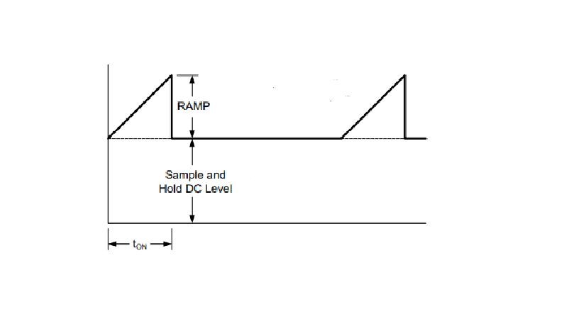
    I am doubting the combination with ramp which is generated by VOS line. 

    If the inductor peak current + ramp, it could be reached the limit. 

    The waveform will be attached on this mail. Strange point is PG goes low even if Vout

    is not decreased so much. 

    Please give your advice. 

    Best Regards, 

    H. Sakai

    (新)Waveform20180424.xlsx

  • Dear, Chris-san.

    Sorry, I missed to write important information.

    This waveform was captured under Room temp(25 ~ 30 deg.C).
    They also measured package top temp, it was around 65 deg.C.
    So there was no possibility of thermal shutdown , I think.

    Best Regards,
    H. Sakai
  • Hi Sakai-san,

    Yes, if you need a -Q1 device, please recommend another IC. TPS62095 is not -Q1.

    Section 8.2.1.2.2 explains how to calculate the peak inductor current. It is not related to input current.

    Do you have the schematic this was tested on? Was it on the EVM?

    The strange thing is that when the IC stops switching, the output voltage does not drop. How much total output cap do you have? What is the load, after PG goes low? (Does this turn off the load?)
  • Dear, Chris-san.

    Thank you so much for all of your advice.

    I found a good information on TI web to solve my big question.

    The waveform was captured on the customer's PCB, but no information about it.

    They are putting big capacitor as 22nF on output. So output voltage does not drop.

    After PG goes low, the load continues ON.

    I think this symptom will be HICCUP current limit ignoring the delay time.

    Can you agree that?

    Best Regards, 

    H. Sakai

  • Yes, it appears to be hiccup.