This thread has been locked.

If you have a related question, please click the "Ask a related question" button in the top right corner. The newly created question will be automatically linked to this question.

CCS/UCD3138A: question about DAC and RAMP

Part Number: UCD3138A
Other Parts Discussed in Thread: UCD3138

Tool/software: Code Composer Studio

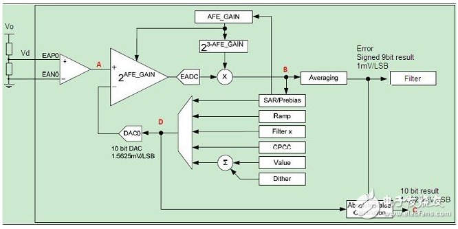
In voltage loop, I can get the A point voltage and set the DAC value though the register of RAMP.

FeCtrl0Regs.RAMPDACEND.bit.RAMP_DAC_VALUE = XX

FeCtrl0Regs.DACSTEP.bit.DAC_STEP = YY

What value i can set? in the picture, the DAC is 10bits. And the register of DAC_STEP is 18bits. is the 4 bits dither ignore?

And the error signed 9bits result is XN. is it right?

  • The DAC_STEP has a 10 bit fractional part, allowing very precise and also very slow ramps. There are 10
    fractional bits, below the dither portion of the DAC. There are 8 bits matching the DAC value, including
    dither.

    For more details please refer to chapter 3.3.3 DAC Ramp Steps in Technical Reference Manual (TRM):

    www.ti.com/.../sniu028a.pdf

    And yes XN is a signed 9 bit value.
    Hope this helps.

    Regards,
  • which register I can use to read the signed 9 bit value? FILTERXNREAD.XN?
    How to calculate the XN form (EAP0-EAN0)? XN = RAMP_DAC_VALUE - EADC? i don't know the register if have the same scale.
  • The best place to read the EADC output is the EADCRAWVALUE in the Front End Regs.  Looking at the XN register you mention is a good way to make sure that the error value is making its way into the Filter. 

    You can also look at the EADCVALUE register.  The ERROR_VALUE bitfield in that register will also give you the EADC value.

    The ABS_VALUE bitfield in the same register will give you the combination of the EADC value and the DAC value scaled at a nominal 1.5625 mV/bit like the EADCDAC.

    Your equation is correct, and they do have different scaling.  The EADC is at a nominal 1 mV/step, and the EADCDAC is at a nominal 1.5625 mV/bit.

    For the full register descriptions, see Section 3.7 in the UCD3138 Technical Reference Manual.

  • In voltage loop control, if XN overflow, what will be happen?
    I have an issue. The output voltage change to 0. For the output volotage change to normal. it need to give a big duty ,but it don have pwm output from UCD3138 PWM pin. And the RAMP_DAC_VALUE is about 0.7V which is set by user. The max value of XN is 2^9*1 = 0.512V. The XN maybe overflow. So i doubt that is the reason. Right?
    Thanks!
  • If the signal goes outside the dynamic range of the EADC, which is what you are describing, the XN will just be at the minimum or maximum level, whichever is appropriate. 

    I suspect that you have something happening somewhere else in the loop.  I suggest that you try on an open loop board, or on a board with the FETS disconnected, and use the CPU SAMPLE function to make sure the rest of the loop is working.