This thread has been locked.

If you have a related question, please click the "Ask a related question" button in the top right corner. The newly created question will be automatically linked to this question.

TPS65218: DCDC1-3 switching freqency on TPS65218

Part Number: TPS65218

Hello  all,

I measured switching frequency on DCDC1 ,2 and 3 of TPS65218 by using osciloscope.

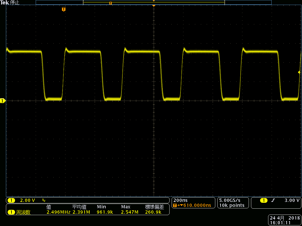
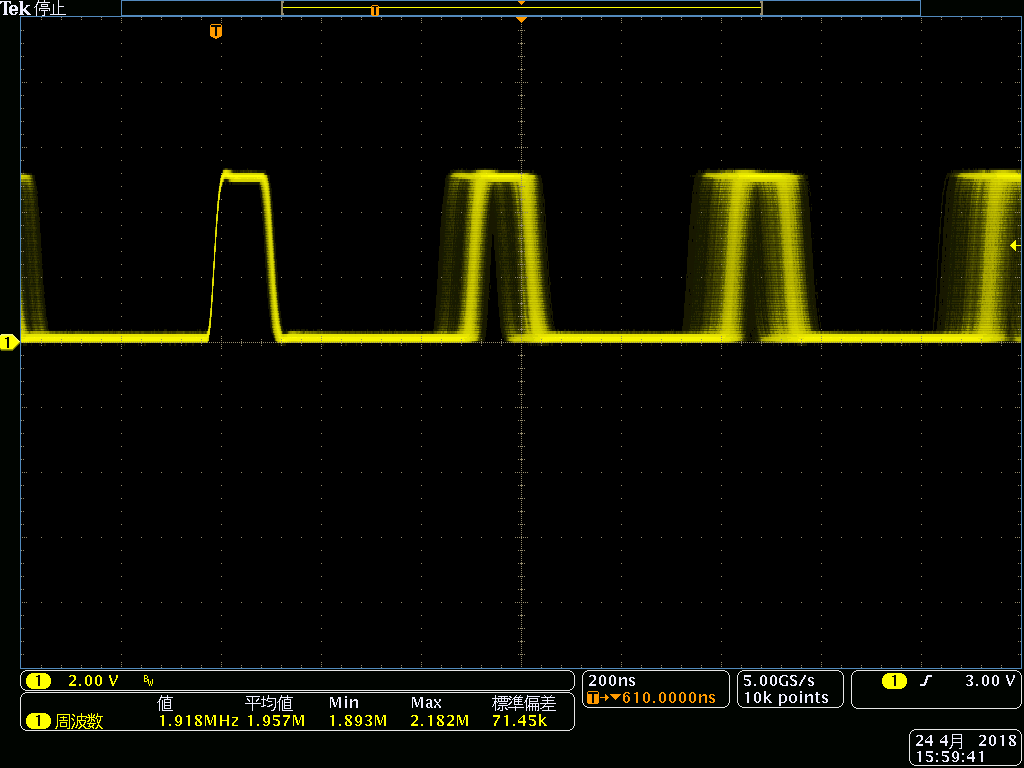
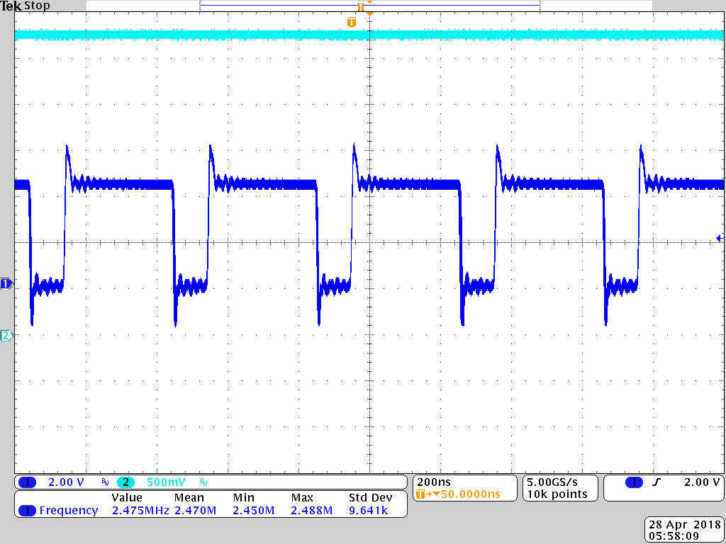
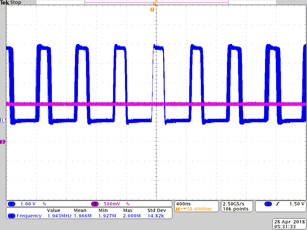
It wasn't stable. These frequency were 2MHz +/- 0.2MHz. It's look like jitter or spred spectrum.

Is it correct behavior? DCDC1,2 and were Forced PWM setting. But DCDC4 is stable frequency.

If correct behavior, Why is it? Can I disable it?

Best Regards.,

M.Iwasaki 

  • Please attach scope shots showing the issue you are describing.

    You can attach images with the switching frequency measured at the output (as a ripple measurement) or at the switching node. Either way is acceptable, but I cannot debug without seeing the issue.
  •   Hello  Brian,

    Thank your replying.

    I attachied it.  1st is the DCDC4.Switching frequency is stable.

    2nd is the DCDC1. It's unstable. Typical frequency is 1.957MHz. Minimum frequency is 1.893MHz. Maxmum frequency is 2.182Mhz.

    It's Forced PWM mode. Please tell me reason.

    Best regards.,

    M.Iwasaki 

  • Iwasaki-san,

    I will ask the same question as I did in the thread related to INT_LDO and DCDC3 (e2e.ti.com/.../2523054).

    Do you know if customer using TPS65218 (ending in -B1 or -B101) or if they are using TPS65218D0 silicon?
  • Iwasaki-san,

    I repeated your tests and the first thing I would like to point out is that this is not the correct use of the term "unstable". The DC-DC converter is not unstable and this cannot be determined from measuring the switching node. The output of the DC-DC converters should be stable even if the clock frequency is not very precise.

    Only the switching frequency of DCDC4 is specified in the datasheet:

    The nominal value is specified as 2.4MHz, and it is not very precise (+/-12% = +/-288kHz) across temperature. At room temp, it is reasonable that the accuracy would be a little tighter and within this range.

    You measured 2.182MHz as a max and 1.893MHz as a min value on DCDC1, and even with these measurements this is +9% from a typical value of 2MHz. But the switching frequency of DCDC1-DCDC3 is not specified in the datasheet.

    My measurements are below using the TPS65218D0 silicon on a TPS65218EVM-100 at room temp and the change in switching frequency was not as bad as your measurements.

    DCDC4 operating as a Buck with VSYS=4.3V with switching node on Channel 1 and DC output on Channel 2 (3.3V):

    DCDC4 operating as a Boost will result in different switching frequencies (not shown here as this question is about DCDC1). The ripple of DCDC4 is also not relevant to this discussion, as this EVM has less capacitance on the output of DCDC4 than recommended.

    DCDC1 with VSYS=3.6V on Channel 1 and DC output on Channel 3 (1.1V):