This thread has been locked.

If you have a related question, please click the "Ask a related question" button in the top right corner. The newly created question will be automatically linked to this question.

TINA/Spice/TPS92410: 50W reference design Cadence Simulation

Part Number: TPS92410
Other Parts Discussed in Thread: TINA-TI, , TPS92411

Tool/software: TINA-TI or Spice Models

Hello,

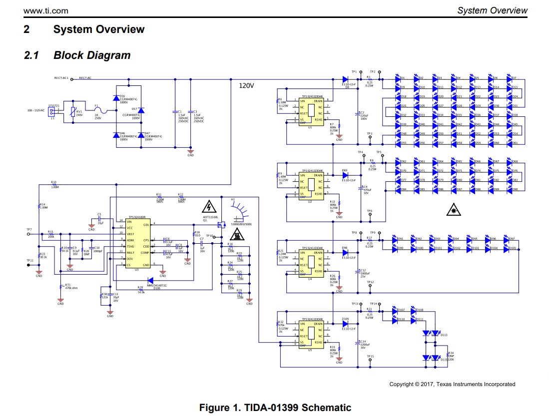
I am a student working on a senior project for an LED company, using the TPS92411 switches and TPS92410 regulator.

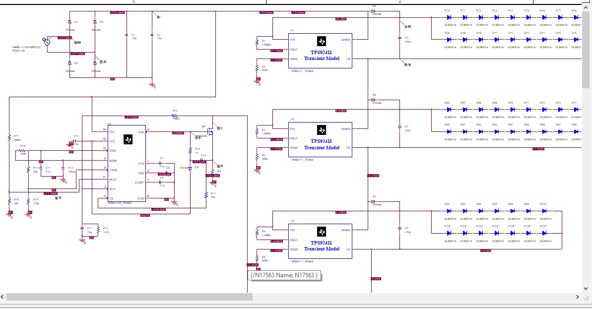
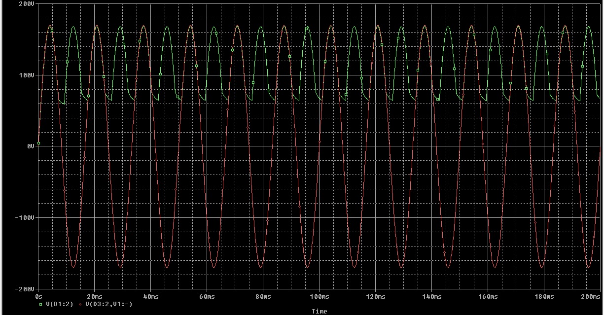
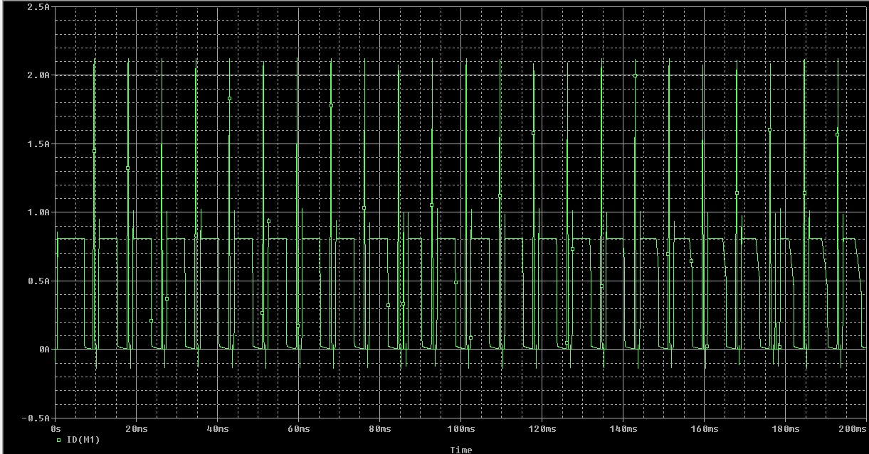
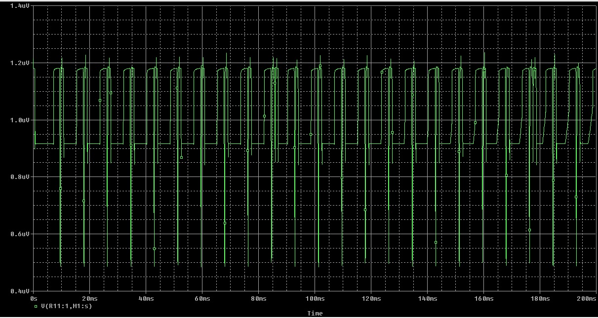
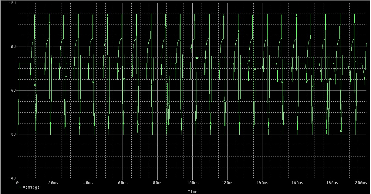
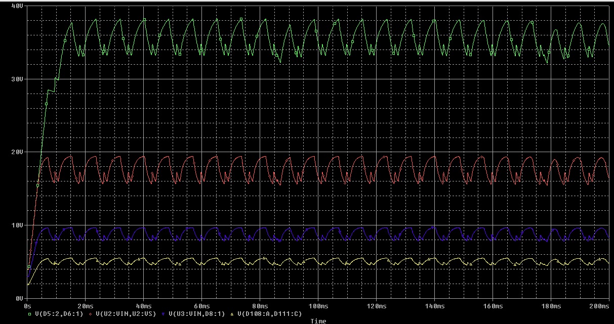
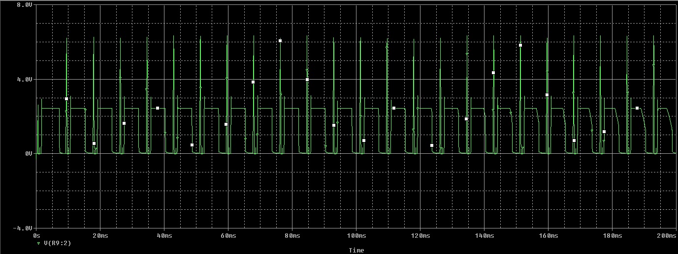
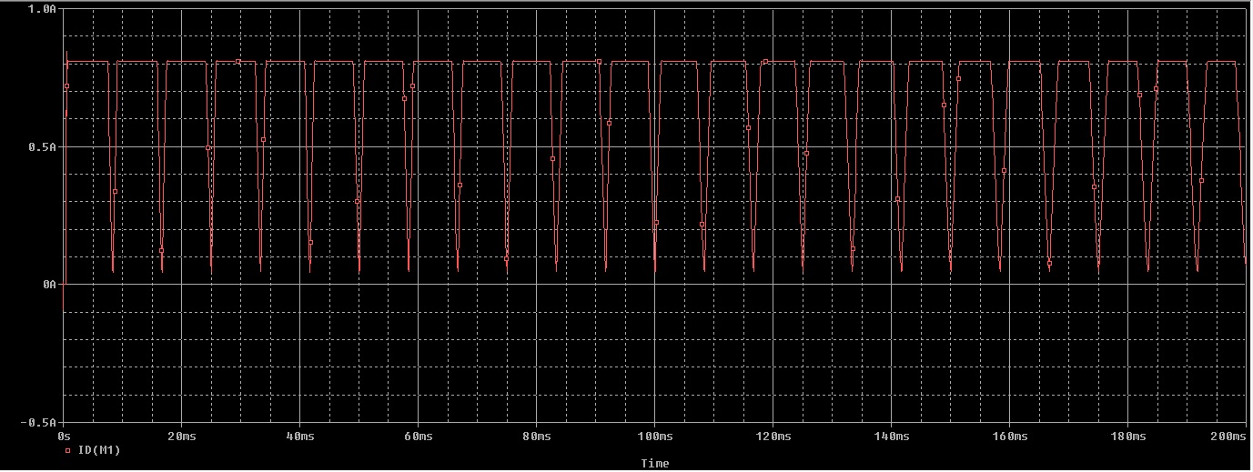
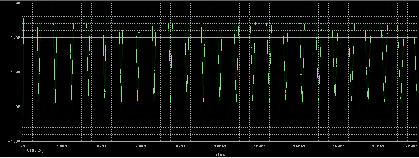
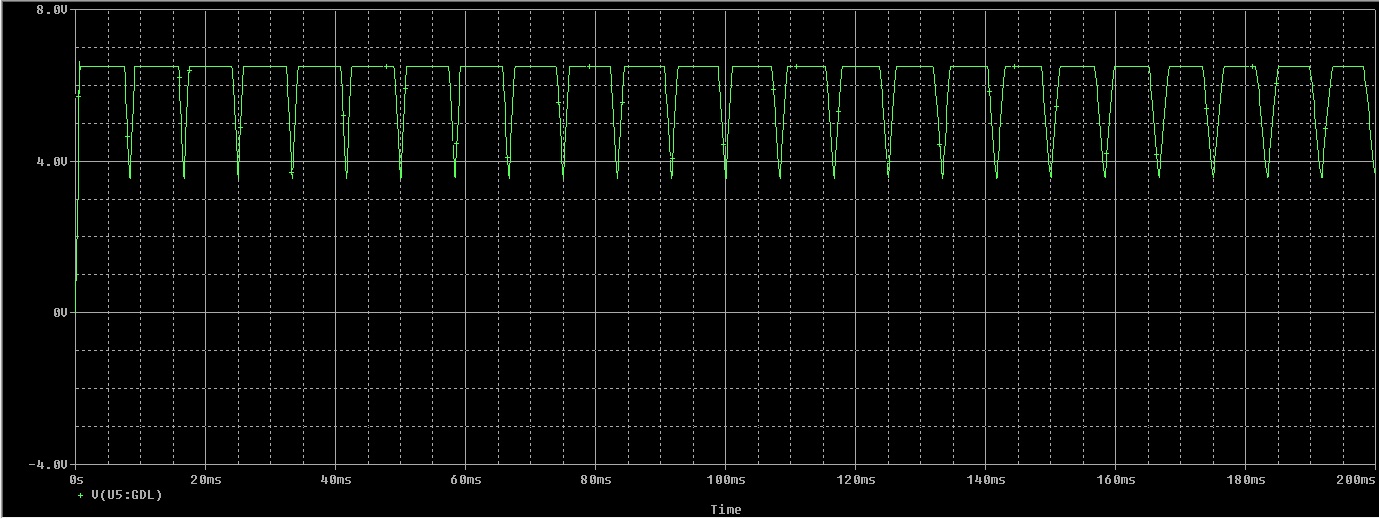
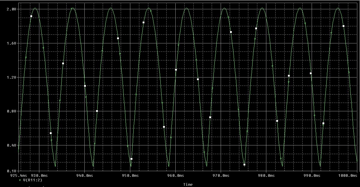
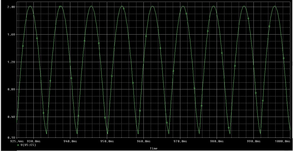
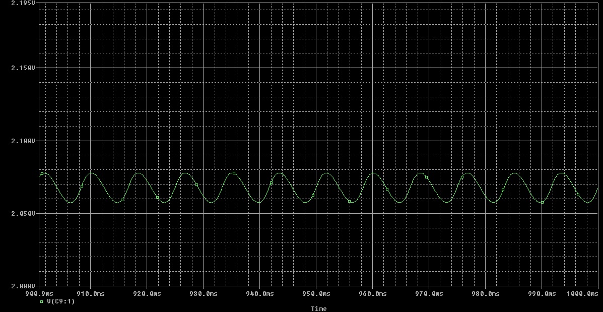
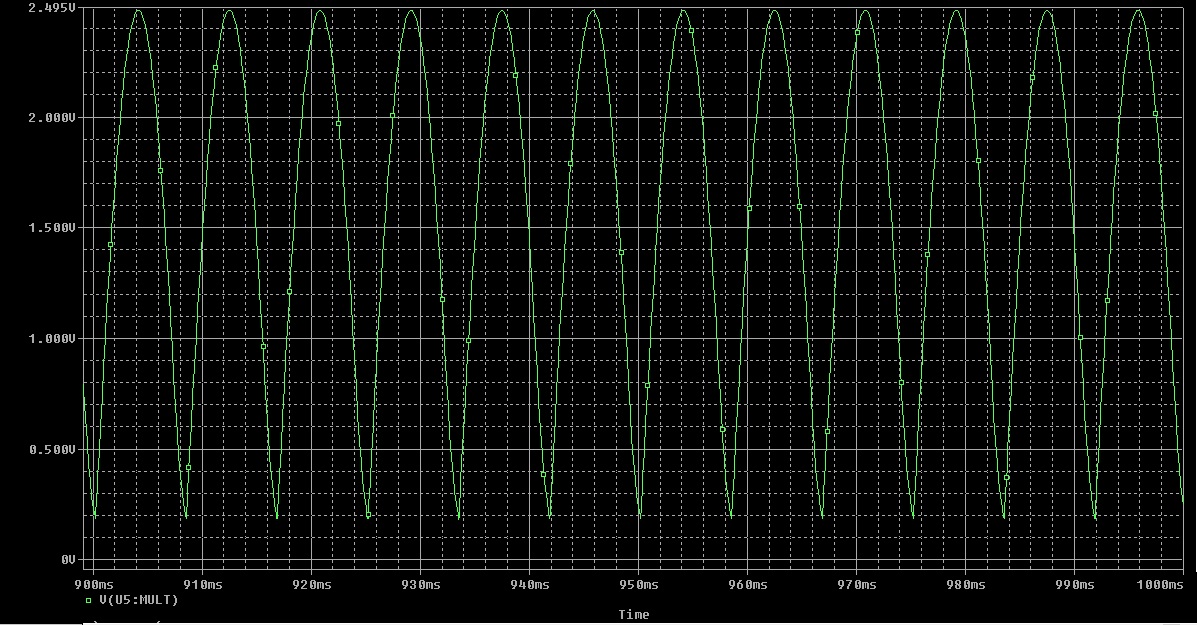
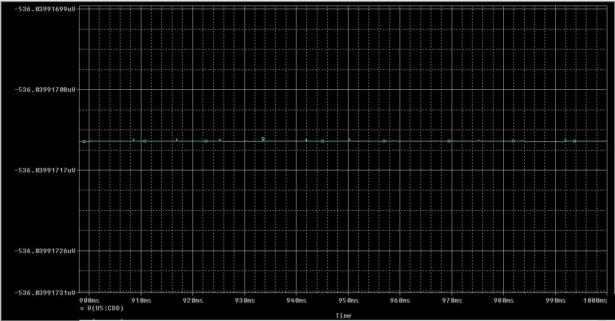
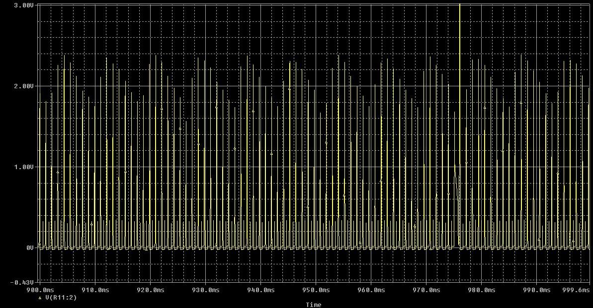
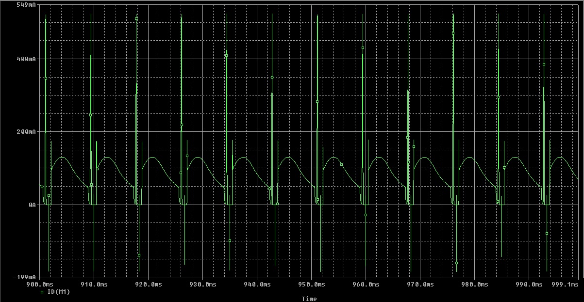
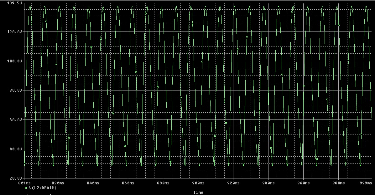
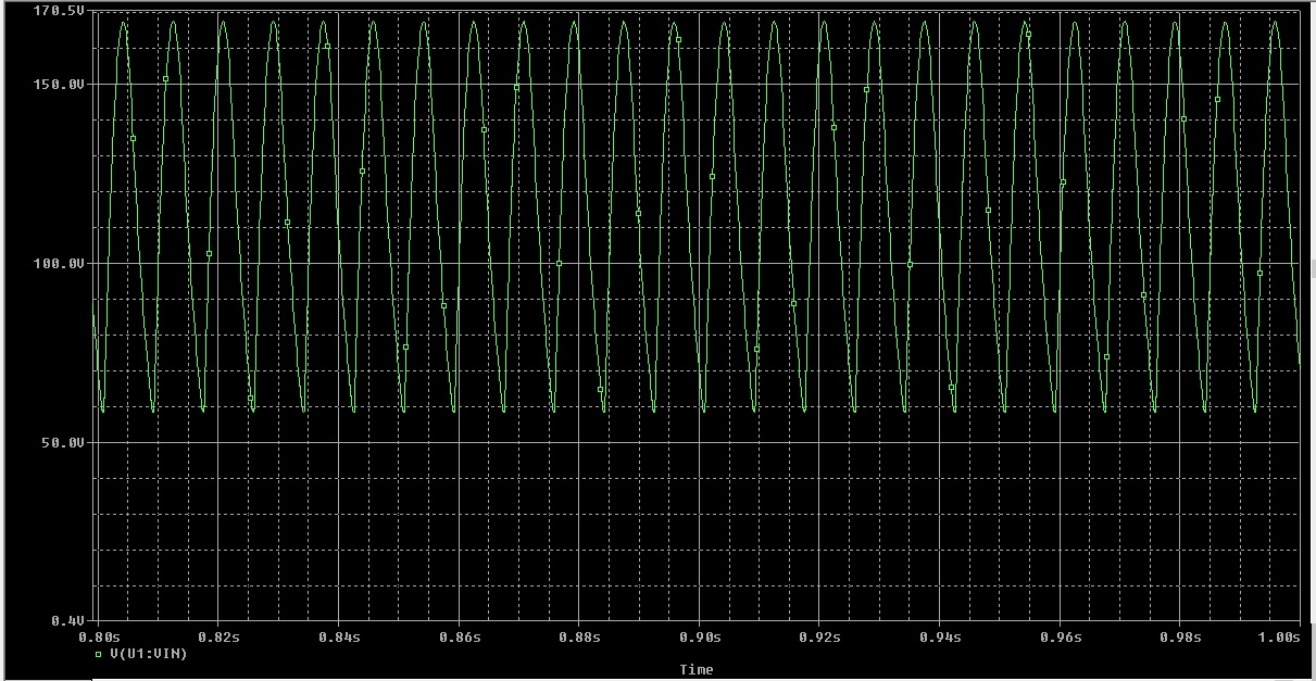
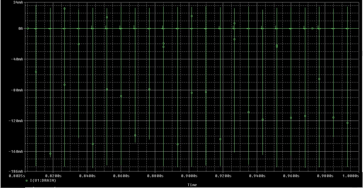
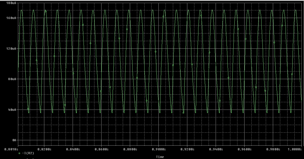
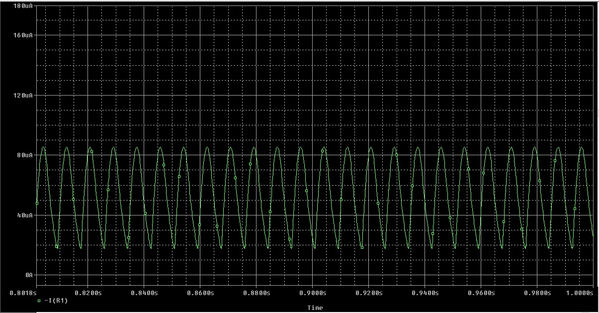
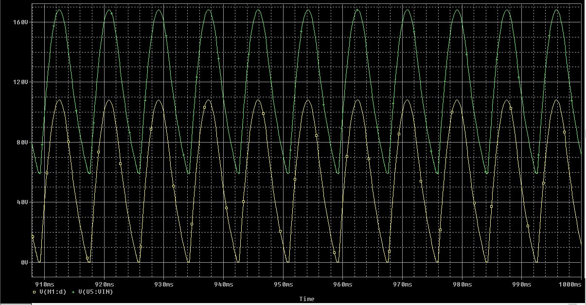
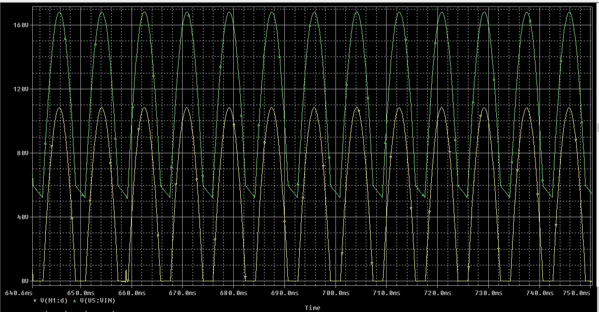
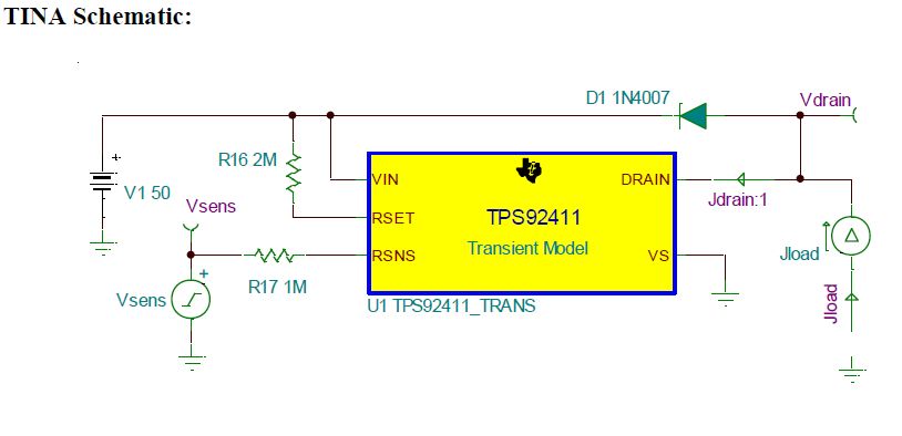
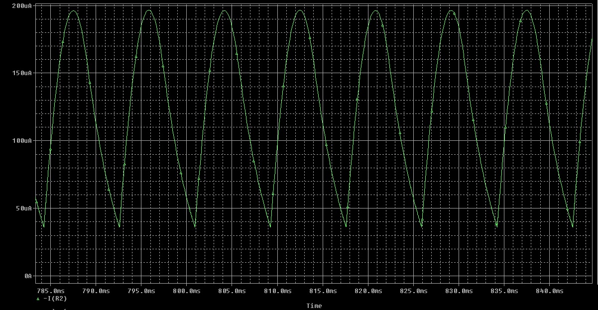
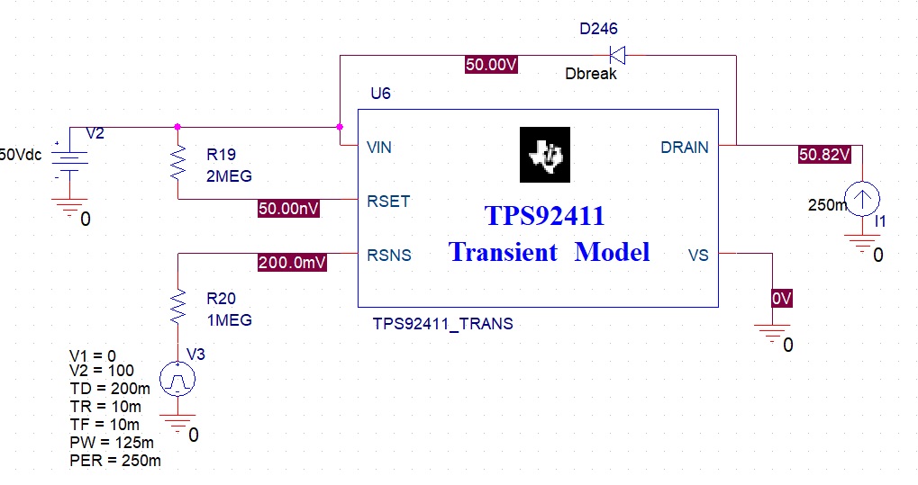
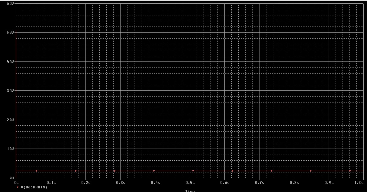
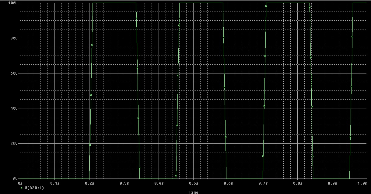
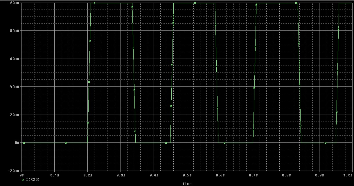
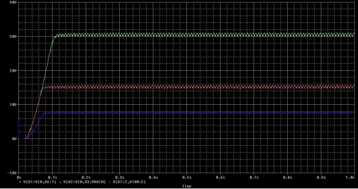
I am attempting to run a Cadence PSPICE simulation of the 50W reference design here (http://www.ti.com/lit/ug/tiducu7a/tiducu7a.pdf), and I do not see any switching on the TPS92411 (voltage across is always 0V, so switch never turns off to allow LED current). The gate control on the 92410 is also not the correct rectified sine wave shape. I am getting no errors about models, I am using the transient models from the TI site for each chip. Is there anything obvious I can check or can I send some screenshots so you have a better idea of what I am doing?

Thank you

  • Hello Miles,

    I will forward this to the expert on these devices.

    Regards,

    Clint

  • Hello,

    Do you have a schematic you are using for this?  I've done only a little with the modelling, TPS92411, when there were issues early on so I know it was working at one time.  The design you are basing this on is one I created.

    Have you looked at the nodes to determine if the TPS92410 is actually regulating current?  I would also check the drain node.

    Regards,

  • Thank you for the reply! Below are the schematics from the reference design and a cropped version of my cadence sim (its is quite large with all the LEDs). I presently see 0V on the drain of the MOSFET and the TPS92410 is receiving the scaled version of the input voltage, but the gate voltage does not follow.  I had attempted MBreak but since it is being used linearly I suspect that will not work. I also tried the M2N6659 from the PWRMOS model and got some current in the circuit, but was still very strange. The gate voltage looked like a triangle at about 660Hz, and it appeared the LED stacks were always on.

    Is there a good (or usable) MOSFET model in cadence that you can reccomend?

  • Hello,

    Can you look at the voltage probe of the rectified AC, what the voltage looks like and the amplitude?

    If the rectified AC is correct the drain voltage of the MOSFET cannot be zero unless the voltage of the LED stacks is too high.

    I have never used Cadence but any appropriately sized N-channel MOSFET should work.  It is running in linear mode so the rdson isn't all that important.  The SOA is important but not for simulation.  Also, when this circuit first turns on the capacitors across the LEDs will have zero voltage on them.  It takes several AC half cycles to get to steady state.

    If you could give me voltage waveforms of rectified AC ('V' at the left top), I of the drain, V of the CS resistor, and any other waveforms that you have or don't make sense.

    You can also just try to apply a DC voltage in the simulation with a current regulator at the bottom to see if the TPS92411 circuit is working.

    Regards,

  • Here is the input AC and rectified AC:

    Here is the current of the MOSFET drain:

    Here is the voltage across the CS resistor (differential across it):

    And the gate voltage is not shaped correctly as I understand:

    And here are the voltage across the LED stacks, which show no switching:

    Thank you for your help!

  • Hello,
    Okay, this helps some since there are some issues here:
    1) The drain current is flat top which could be that the dimmer detect put it in DC reference mode however 2 next may be causing the issue.
    2) The voltage on the current sense resistor is incorrect. If the drain has 0.8A running through it the resistor should have much higher voltage across it unless the value is wrong (low) or the simulation is not correct.
    3) The gate voltage somewhat makes sense. I'd like you to try something to try and get the TPS92410 portion working first, see below.
    4) The led stack voltages are too low but that's not what is contributing to your problems (yet).

    I would try bypassing the TPS92411s, connect the MOSFET drain to the rectified AC bypassing all of the TPS92411s, this was we can try and get the waveforms looking correct on the TPS92410 first. You may have to remove R13 (I think it's R13, not real clear on the schematic, but it's the upper divider resistor for DOV). Check the CS resistor, something is wrong there, the voltage should be much higher across it, this may also be why the current doesn't look sinusoidal, it may not even be regulating. The CS voltage should have a peak of the half sine of about 2 - 2.2 volts (I'd have to go back and find out exactly what that is but it's no where near that at 1.2 uV. I cannot read what the CS resistor value is. Also, try setting it to 10 ohms. It should be around 3 ohms (18.2 ohms/6). If I recall correct the TPS92411 model may not work at higher currents (abouve 500 mA) but we'll find that out later.

    Regards,
  • I will try the TPS92410 by itself next, but for right this moment I believe I scoped the wrong voltage for the RCS. Below is the voltage across the resistor from the FET source to ground, it is 3 ohms presently. I will remove (open)  R13 (the upper resistor in the DOV divider, presently 4Mohm) and short across the switches and try again.

  • With the switches bypassed, it seems the regulation may be working.

    here is the drain current:

    Here is the RCS (3ohm) voltage:

    Here is the gate drive:

    Does this seem correct? Thank you

  • Hello,

    This is better but something is still not correct.  It should look sinusoidal (at the half wave level) and the amplitude is too high.  In dimmer detect it should be 1.5 volts DC, in PFC mode it should be 1.291 volts which would be 1.83V at the peak of the half sine (1.291*1.414).  Could you look at the CS pin on the IC and see if it's the same amplitude?  Can you also probe Comp, Mult, CDD, ADIM and TSNS.  Also, can you also run the simulation longer on the above plots, if you look it's not settled out, it may be heading to correct operation as the flat top of the waveforms are getting smaller at time progresses.  If this is the case maybe there's an initial condition causing something.  Comp waveform may show that.

    Regards,

  • You are correct it was not settled as I had thought. These captures are the last 100ms of a 1000ms simulation. The amplitude of the RCS did settle down to about 2V.

    RCS:

    CSpin:

    COMP pin:

    MULT pin:

    CDD (close to 0):

    ADIM pin:

    TSNS:

    Thank you!

  • Hello,

    Looks like that part is working correct. Now the TPS92411s have to get figured out. FYI, the bottom TPS92411 will not work as it is since the LED stack voltage never gets high enough for the TPS92411 to operate but I wouldn't worry about that for now. I'd just try adding one or more of the LED stacks back in.

    Regards,
  • Okay, that is good news. Thank you for the heads-up on the bottom stack. I made this LED model to match  the IV curve of the reference design but it may not be working as I think.  

    Here is the full sim of the voltage across the first three stacks (with them all added in for now):

    and the last 200ms steady-state:

    And here is the RCS

    What is the best way to verify the 92411's now that the 92410 is verified to be working?

    Thank you

  • Hello,

    So, I recall when they created the TPS92411 model it might have been limited in current so the first thing I would try is changing Rcs to 10 ohms instead of 3 ohms just to see if it starts working. Note it make take longer to settle out with this change, maybe not. It will take longer to charge the capacitors across the LEDs due to the reduced current.

    Regards,
  • Okay, I tried 10 ohms and 14 ohms, with a similar output. It has a more sinusoidal shape and less spikes now.

    and here is the drain current

  • Hello,

    One thing, since the LED stacks aren't near what they are supposed to be the Rset resistor values will be off. It should still switch though. Perhaps this has something to do with the TPS92411 VS pin not being referenced to GND (which it cannot be) but the simulation may not be happy. Can you look at the voltages of at least one VS of the TPS92411 and Vin. Also check the drain current of one of the TPS92411s (maybe the top stack for these since the voltage is the highest). I cannot see the schematic very clear but the Rsns resistors are supposed to be 806 Kohm, the Rset resistor value depends on the stack voltage, top is 1.5 Meg, next is 1.4 Meg, then 1.24 Meg.

    If you can measure the current in Rsns and Rset we can see if the thresholds for tripping are being met. On the falling rectified AC edge crossing 4 uA in Rsns.

    Regards,
  • Okay, the resistor values are as you say, and can be adjusted later but i will likely fix the LED model to get the correct size stack once we can get some switching action.

    VS pin:

    VIN pin:

    DRAIN current:

    Rsns current:

    Rset current:

    is the 4uA threshold mean it must go below 4uA? The Rsns current now has an offset far above that. 

    Thank you for the continued help, I was very stuck and really appreciate it.

  • Okay,

    I think this is related to the LED stacks being too low voltage wise. Try removing/disconnecting the two 1.5 uF capacitors across the rectified AC, looks like C1 and C2, and see what happens. Also get a picture of the main MOSFET drain voltage before and after removing those capacitors. Those capacitors are for conducted EMI reduction.

    Regards,
  • I have tried a few things, and removing those capacitors causes convergence errors with the simulation. I am working to see if I can fix the LED model I have made or if there is another with a drop that is correct. Unfortunately LED options are very limited in cadence, it is odd.
  • Hello,

    Try dropping the value very low, try 0.01 uF or even smaller.

    I want to see if the capacitors are part of the problem or there's something else, I'm guessing there's something else but have to try things.

    Also, forgot to ask, what is the RDSon of the Main current regulating MOSFET?
    Thanks,

    Irwin

  • It is 2ohms for the RDSon of the main FET. This value is from the datasheet of the actual part the model is based on.

    the smallest I could make the caps without error is 0.1uF, but there is still no switching. i also tried adding more LEDs to the top stack until it reached 80V but also saw no switching.

    MOSFET drain voltage (yellow) and input rectified (green) before cap change:

    after cap change:

    Thank you

  • Hello,

    So I wanted to try this to see if it was a TPS92411 issue something with the current regulator.  It's obvious that the TPS92411s are not switching even after crossing the 4 uA threshold or Rsns.  If you measure the current through Rsns I would guess it's dropping below 4 uA which means it should switch.

    I'm thinking this may have to do with the VS not being referenced to GND in the simulation.  Maybe try simulating a single TPS92411 with VS ground referenced with a current source going to the drain clamped by a or diode clamped to Vin as the SCH shows.  Provide Vin to the TPS92411 and see if it switches (see picture for simulation test).  The Rsns step has to be rather large, say 0 to 100V a few cycles to see if it switches (maybe even a triangle waveform to see the levels where it switches).

    Regards,

  • Just to make sure I understand, the current in the Rsns should dip below 4uA to switch? right now they do not (see plot)

    Also, I will run a simulation of the schematic below, should I see switching on the DRAIN pin? Is 250mA a usable current value for the current source? And do I need any rectified AC signal or the current regulator or this is a way to test the 92411 on its own?

    Thank you

  • I simulated this schematic

    and got this on the drain

    with this Vsens (as labeled on your schematic)

    and this Rsns current

    I have read through every document I can find on the 92411 and cannot see any obvious problem. Perhaps my thresholds aren't set as I thought, but I am unsure.

    Let me know what you think or if I need to alter this sim

    thank you

  • Hello,

    Interesting that the TPS92411 switch is just on in this simulation but in the other they are off.  I found an old email when I was looking at the TINA simulation of the TPS92411.  I ran it and it works so if you can get me your email address I'll send it to you.

    Regards,

  • Hello,

    The circuit above should work, the TPS92411 switches based on the current it sees from Rsns and for Rset threshold it's 1/2 of the current through Rsns (there are some offsets involtage, 200 mV for Rsns adn 1.2V or so for Rset.

    250 mA is fine for the TPS92411 drain. The 50 nV on Rset is this a probe of that voltage? The Rset voltage will change depending on the Rsns current (or be clamped on the high end). As the current increases the voltage will fall and cross the 1.25V threshold and cause the switch to open.

    Current needs to cross 4 uA for the TPS92411 to close.

    Regards,