This thread has been locked.

If you have a related question, please click the "Ask a related question" button in the top right corner. The newly created question will be automatically linked to this question.

TPS53355: current limit

Part Number: TPS53355

Hi

I have some question about current limit. It may be a basic question regarding to DCAP.

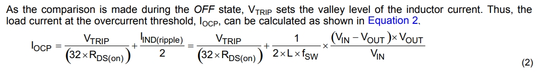
The current limit is comparison with IOCP set point during the OFF state .(Low side Fet is ON). It is a valley level of the inductor current.
On the other hand, it looks the top of the inductor current is compared at the following equation. ( IOCP= (VTRIP/(32*Rds)) + (IIND(ripple) / 2) )

Why the top of the inductor current is not compared but it is the valley of inductor current?

(Please correct me if my understanding is not correct.)

Best Regards,

Koji Hamamoto

  • Hamamoto-san,

    TPS53355 does use valley current detection for OCP. The Equation 2 in the datasheet gives the average current that results form the valley detection. The first term, Vtrip/(32*RDSon) gives the valley detection point. The second term, Iind(ripple)/2 adds back on halt the p-p inductor ripple current to get the average load current at the current limit trip point.
  • Hi John-san,

    Thank you for your support as always.

    I understood. So, the IOCL is an average load current. I thought it was a peak current.

    On the other hand, I have a question about this current limit topology. (valley current detection)
    As you mentioned, Vtrip/(32*RDSon) is given the valley detection point of the inductor current. Because the GND pin is used as positive current sensing node and LL is used as the negative current sensing point. That is why the above equation is given the valley point.
    Generally, the peak current sensing is used as the current sensing. However this device is detected the valley point of the inductor current. Why dose the device adopt such the current sensing topology? (cost? or other reason?)

    Best Regards,
    Koji Hamamoto
  • Hamamoto-san,

    Valley current limit keeps the on time constant while extending the off time to reduce current below the limit. So it would be natural to think of using this type of current limit in converters using constant on time control modes.   Constant on time control sets the on time to a fixed value and uses a hysteretic comparator to end the off time when the fed back portion off the output voltage falls below a preset level. The valley current limit will override this control signal if the current is above the limit, increasing the off time. So here we come to an advantage of valley current limit over peak current. Valley current limit is applied at the end of the off time, before any switching transition. There is no need for any blanking time.

    Another consideration is the physical location of the sensing circuit. For current limit, the actual current is not used, but instead it is a voltage proportional to the current. This may be derived directly from the respective switch or more typically from a smaller mirrored element. For current mode control, this sensing element is at the high side switch and is sensed relative to the input voltage rail. The input voltage may be variable of a large range and may also have significant ripple. Valley current limit on the other hand senses the low side switch current and the sensing element is referenced to the much quieter and constant circuit ground. While this is an advantage, it does have a significant limitation as well. Since valley current limit senses current at the low side switch, it is generally limited to synchronous converters.

  • Hi John-san,

    Thank you for your support as always.
    I understood.

    Best Regards,
    Koji Hamamoto