This thread has been locked.

If you have a related question, please click the "Ask a related question" button in the top right corner. The newly created question will be automatically linked to this question.

UCC28950: Resolved UCC28950: How to avoid cycle-by-cycle current limiting in soft start

Part Number: UCC28950
Other Parts Discussed in Thread: UCC28070

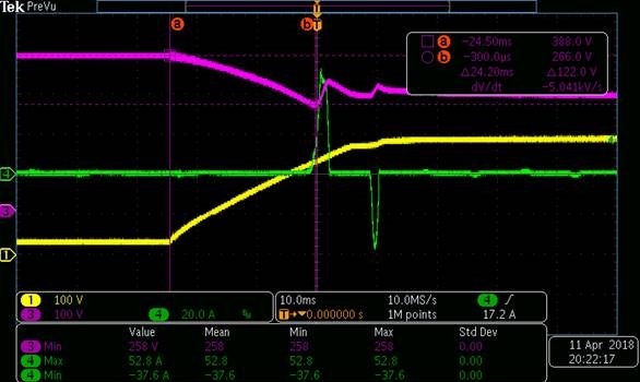
  I have a question is about UCC28950 soft start function , The enable pin  which from Pull up threshold (3.6V) to SS clamp voltage(4.65V), the UCC28950 will fast pull up the output voltage to design value 325Vdc , and the input current will clamp with cycle by cycle limit .The enable function show as Fig-1.  I think the two questions as below:

  1. The current limit function in normal operation should not occur , but it will occur in soft start.
  2. For normal operation design margin , I design the current limit point to avoid the noise to trigger the protection occur in normal operation.


Vi = 90~264Vac transfer to 387V which use UCC28070 to be the PFC solution

Input current ≒7A

Input power = 2.7KW

Vo = 325Vdc

Current limit design point ≒15A

UCC28950 work in voltage control mode


My question as below:

The current limit protect shouldn’t occur in normal operation condition including start up status .Did you have some method to avoid UCC28950 fast pull up function?

I think smooth start up is better than fast start.

I have try some adjustment to avoid the current limit occur:

  1. I add additional 5V to pull up the enable voltage to avoid current limit occur, but it’s not improvement.
  2. I  put the soft start capacitor in 100nF to make the soft start more fast , I think it can avoid the current limit occur , but it’s not improvement.
  3. I try to put the RT_min =49.9KΩ , let the burst mode to avoid the current limit , but it’s not improvement.(The RT_min as the Fig-2)


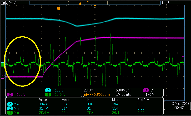
The Fig-3 shows the input inrush current will make the input voltage down to input UVP protection occur, and it’s happen in output start up.


                                                                Fig-1


Fig-2


                                                                Fig-3

CH1:Output voltage                                                                       

CH3:BUS voltage

CH4:Input current(AC side)

  • Hello Spike

    I think the problem is with the PFC stage and not with the UCC28950 because the current spikes look like they are 10ms apart - this could be due to direct conduction from the input of the PFC stage to its output. If the output falls below the peak of line voltage then you get uncontrolled current flow from input to output for that part of the line cycle when Vin is greater than Vout. Test this by seeing if the current spikes happen when Vac is greater or equal to Vout.

    The fast pull up feature cannot be disabled and in any case it happens after the soft start ramp has completed.
    Can you increase the UCC28950 soft-start time - try to double the capacitor and see if the inrush becomes less of a problem.
    Slowing the soft start will reduce the transient load on the PFC stage.

    Please note that the UCC28070 has an enhanced transient response (sect 7.3.11 in the Data Sheet). This should prevent the output voltage of the PFC stage getting so low but this feature is disabled during the PFC stage soft start. Can you use the SS/EN pin of the UCC28950 to delay its start-up until after the UCC28070 has come out of its soft start process ?

    Regards
    Colin
  • Hi Colin,

          I see the duty will increase in soft start , the duty will be maximum in soft start function , and the waveform as below:

    CH2:Main transformer V(for observed the duty variable)

    CH3:PSFB Vo

    CH4:PSFB input current

    I use DC source to be PSFB(UCC28950) source, and the DC source has the same status. The DC source input current spike shows below:

    CH2:PSFB Vin

    CH3:PSFB Vo

    CH4:DC source input current


    I think the problem as below:

    1. The UCC28950 duty will be maximun in soft start function , I think the soft start should be soft to build output voltage.

        Could I make the duty in minimum (like burst mode duty) to finish the soft start function?  Could I set the duty in soft start?

    2.  This product is start up flow chart as below:

    check AC input good -> PFC start -> check PFC Vo is good -> PSFB enable -> PSFB Vo is good

    The PSFB will in soft start function after PFC build up , and PFC Vo is good.

    3. Input voltage will pull low to 312Vdc when UCC28950 in soft start , The 312V will make PFC under voltage protection occur. Now I turn off the PFC UVP to make UCC28950 build up Vo , but I think I turn off the UVP isn't right, isn't it?

  • Hello Spike

    I still think you should slow up the SS ramp by increasing the SS capacitor. 

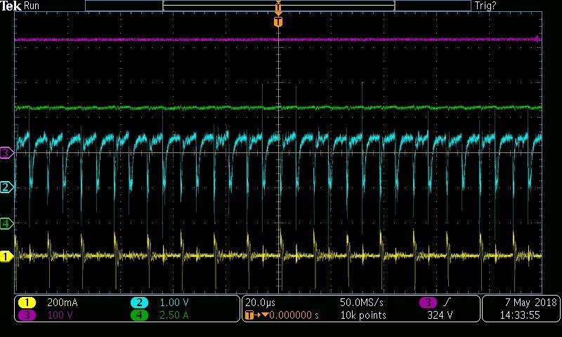
    I also wonder why the current spikes are present before you start the UCC28950 - spikes in yellow circle below. If the UCC28950 is not turned on then there should be no current spikes.

    Do  you have an electronic load that you can put on the output of the PFC stage instead of the UCC28950 ?

    Regards

    Colin

    o Spike

  • Hi Colin,

              The figure(yellow circle) as you see is the system power current , not from the PSFB.  My system turn on procedure as below:

    1) Turn on AC source

    2) Turn system power which provide all block start up , include UCC28070 start up .

    3) Turn on UCC28070 EN pin.

    4) When every block is good , I will turn UCC28950 SS/EN pin to build up Vo . 

    Because I want show the problem is not from PFC , so I use the DC source to substitute PFC block.The block like below:


    1) Turn on the DC source . 

    2) Turn on system power which provide all block start up , include UCC28950 start up .

    3) Turn UCC28950 SS/EN pin to build up Vo . 


    I have slow up the SS ramp by increasing the SS capacitor from 0.47uF to 4.7uF , but the result look the same . The figure as below:

    CH2:UCC28950 EN/SS pin

    CH3:Main transformer volt

    CH4:PSFB input current

    This is Css=0.47uF

    This is Css=4.7uF

    I have an electronic load , and I can put on the output of the PFC stage,  but I need to know which you need to know. ( ex: PFC output V / I ,  or other thing)

  • Hi Spike

    I'm still confused and unclear about what is happening here but I would make the following comments.

    1/ The input current to the PFC stage should be sinusoidal when it is loaded. At no load there should be virtually no current in the PFC stage input. The current spikes which I circled in yellow should not exist. Please show me where this measurement is being taken - a simple block diagram is ok.

    2/ If the SS/EN pin of the UCC28950 is held to 0V then the PSFB input current should be 0A. Again, the current spikes you show in first image of your last post should not be present.

    3/ In SS, the duty cycle initially starts at a low value and is increased steadily at a rate set by the capacitance at the SS pin. Can you post a screenshot of the waveform at the CS pin during the SS ramp. Two horizontal scales please, one at 10ms per div and another at 20us per div

    4/ If you start the PSFB from a fixed DC source, then can you probe the PSFB input current. The PSFB load current, The PSFB Output voltage and the CS pin of the UCC28950.

    Regards
    Colin
    Please note: Monday 7th May is a public holiday in Ireland. I'l be out of office.
  • Hi Colin,

                  I think it's my mistake.

    1) and 2)  The circle in yellow in Figure-1 which I measurement is the power line as Figure-2 block shows , and I have not use UCC28070 PFC block .I use a DC power source to substitute PFC problem.             

    Figure-1


    Figure-2

    3) The SS pin and CS pin waveform as below:

    Css=4.7uF

    CH1:28950 SS pin

    CH2:28950 CS pin 

    CH3:PSFB Vo

    CH4:PSFB Iin

    10ms per div 

    Figure-1

    20us per div

    Figure-2

    4) I start the PSFB from a fixed DC source, and I probe the PSFB input current. The PSFB load current, The PSFB Output voltage and the CS pin of the UCC28950. The waveform as below:

    CH1:PSFB output current

    CH2:UCC28950 CS pin

    CH3:PSFB Vo

    CH4:PSFB input current

    10ms per div 

    20us per div

  • Hi Collin,

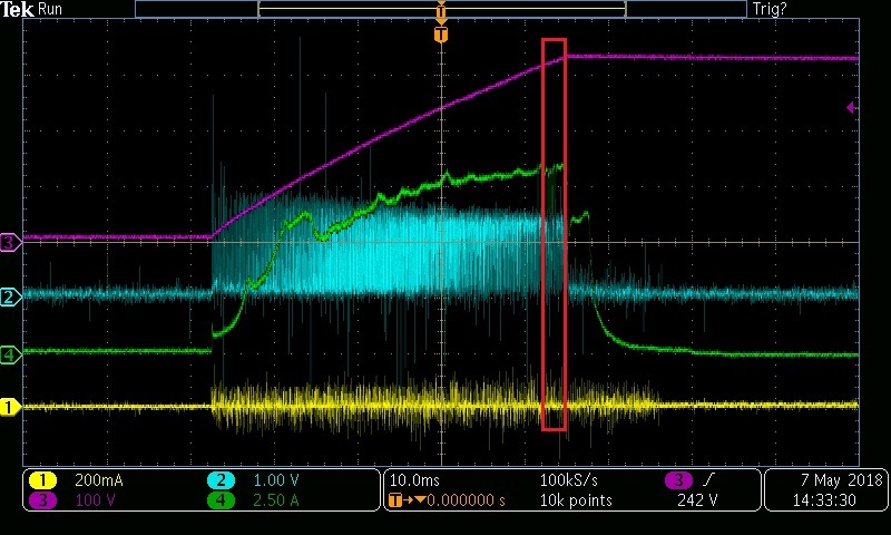
           I have another test which is about adjustment the PFC output to make PSFB start up , and it has the same problem. The problem is the input current is over my system input spec.

    The Figure-1 shows the waveform Channel 4:PFC Iin measurement point  

    Figure-1

    CH1: UCC28950 SS/EN pin

    CH2: PFC Vo

    CH4: PFC Iin

  • Hello Spike

    My colleagues will organise a conference call shortly - in the meanwhile here are some other things you can try.

    Please send me the PFC and PSFB schematics - you can email them directly to me at colingillmor@ti.com

    Please note that the as the PSFB output voltage rises there MUST be some transient current. This is needed to charge the output capacitors of the PSFB and to supply whatever DC load is present there. The peak amplitude of this current will depend strongly on the speed of the SS ramp which determines the dv/dt at the PSFB output and hence the current into the output capacitance (and of course into any capacitance that may be present on the load) –

     The PFC stage must either – supply this current from its output capacitors or pull it from the AC source.

     What is the customer’s peak inrush current specification ?

    The peak current in the waveform below is only 15.4A – PFC inrush currents when line is first applied can be over 100A.

    Can they take a plot of the SS/EN pin – Ch2 below is the PFC output voltage.

    The current spikes could be due to direct conduction from PFC input to Output – this can happen if PFV_Vout is < PFC_Vin. Do they see the same effect if they reduce the AC line voltage to 120V ?

    Regards
    Colin