This thread has been locked.

If you have a related question, please click the "Ask a related question" button in the top right corner. The newly created question will be automatically linked to this question.

LM5118: Possible load regulation issues at high end of transition mode

Part Number: LM5118

Hello,

I am using an LM5118 circuit with the following characteristics and part values:

Vout = ~21.4V

Fsw = 491.5kHz (i.e., 10kohm timing resistor)

Rsense = 8 mohms

Cramp = 470pF (chosen at the next standard value below the calculated recommended value due to the high output voltage and need for additional slope compensation as discussed in the datasheet)

VCCX = ~10.5V

The compensation network is such that the calculated Phase Margin in both buck and buck-boost is solid.


A few devices have recently exhibited the following behavior described below.  I'm trying to determine if it's just a bad batch of ICs (on 1 of the few, the IC was replaced and the behavior went away), or if there is a design issue I need to be addressing that is making things marginal.

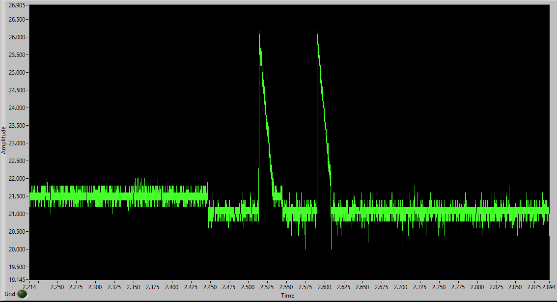
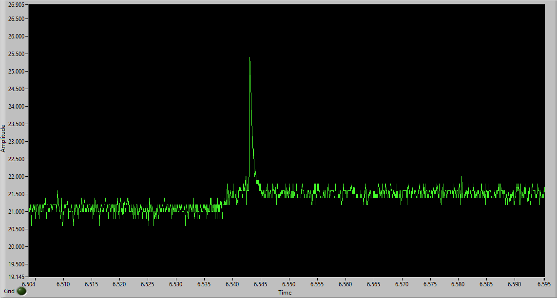
When switching from a light load (less than 100mA) to about a 7 ohm load, the voltage dips a few percent and stays there until the load starts to decay (i.e., slowly turn off over a few ms).  At that point, the output drifts back up before spiking by several volts.  It can also spike by several volts immediately upon the load being removed quickly as well. 

This behavior has occurred at input voltages ranging from about 27.4V to 28.2V.  Granted, at the highest end of that range, the voltage doesn't dip the few percent, but it still has an excessive spike when removing a load, compared to normal behavior.

Here are some screenshots of the output voltage.  The first is when the load is applied, with some intentional "bounce" of the load being removed and reapplied to show the excessive spike.  The second is when the load is decaying, showing the drift back up and spike.

Is there a good explanation for this type of behavior?  Or did something break inside the ICs?

Thanks,

John

  • For some reason, the screenshots didn't load.  Trying again...

  • Hi John,
    The scope pictures are not accessible. Could you attach again?

    Thanks,
    Youhao
  • Youhao,

    That's odd.  I can see them in the thread.  But I'll try it again a different way.  The screenshots are below.

    Thanks,

    John

  • Thanks. I can see them now. The 2nd waveform looks like the typical output response when you have fast step down of the load, and the spike is usually mainly caused by the ESR and ESL of the output capacitor. The current from the inductor cannot change instantaneously with load, and the extra current must flow into the output capacitor.

    The first picture looks weird. Having that voltage spike on the Vout, there must be a big current. How do you switch over to 7Ohm from 100mA load? Using a relay? If you are using a relay, it may bounce and causing the sudden load disconnection, and force the circuit to behave like in the 2nd picture.

    Anyway, it seems your output capacitor has high ESR and ESL, which can be the component property issue, or the layout issue. A good capacitor placed in a poor layout can produce such large transient spikes.
  • Thanks for the reply, Youhao.

    The 2nd waveform is a slow step-down of the load (~7ms fall time), so the spike wouldn't be considered normal in that situation.
    The total ESR of my output capacitance is under 10mohms and our layout would not add much ESR or ESL to it (makes use of plane shapes to connect parallel capacitors together).


    What also looks weird in both pictures is the output voltage dipping by ~.5V (and staying there) in response to the load. You are right that the 2nd waveform has bounce. I actually did that on purpose. At other input voltages (either higher or lower than the 27.4 to 28.2V range that I mentioned), there is no persistent dip under load, and there is minimal overshoot or undershoot when stepping the load up or down fast or having bounce in the load connection.

    Replacing the LM5118 IC got rid of the unwanted spikes and dips that occurred within that input voltage range.  Would that point to a bad IC, or is there some sort of tolerance in the IC that my design might be susceptible to?

  • Hi John,

    A bad IC came to my mind initially but there was not enough info to blame the IC. The IC is sensitive to ESD during handling. Normally an ESD wrest strap should be worn when soldering, probing and handling the circuit. Pay attention to the operating conditions when the same issue shows up again, which can give us a clue of how it is damaged.

    Thanks
    Youhao
  • Thanks, Youhao. I'll consider this resolved for now. What kind of operating conditions did you have in mind besides what I've already provided?

    Thanks,
    John
  • Hi John,

    I mean the Vin, Vout, Iout, and any particular actions applied to the circuit just before the failure occurred again.

    Good luck and thanks,

    Youhao