This thread has been locked.

If you have a related question, please click the "Ask a related question" button in the top right corner. The newly created question will be automatically linked to this question.

LM5145: can not start up under low temperature in no load

Part Number: LM5145

Hi,

My customer designed a 24Vin to 16Vout/6A DC/DC by LM5145. It works well in room temperature and the load transient response is fine. However, when it works under -25C ambient temperature, all the 50 prototypes can not start up properly even in no load. The output voltage remained as 9V in this situation.

We tried below measures, but all did not solve the problem.

1. Demount EC6=1000uF to reduce the output capacitance;

2. Set higher I limit by Rilim, or even disable current limit by demounting Rilim. The DC/DC works well in room temperature in no and full load, but the issue still exists in -20C temperature. We have a 100pF capacitor on ilim to filter the noise;

3. Modify the compensation on comp pin;

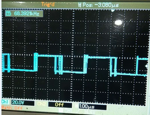
Below figure is the high side drive (HO) in -25C. It is not stable.Tomorrow I will enable the diode emulation to see its effect. I will also check the VCC voltage in -25C. I would like to listen to your comments.

I need your advice for this issue. Thanks very much!

  • Hello Jerry,

    I will direct your question to the supporting Engineer.  Thanks.

    David.

  • Hi Jerry,


    The ILIM RC filter is not set correctly – it should have a time constant of 6ns as advised in the datasheet. Also, the resistor in series with the VIN pin is missing. More important, there is a secondary winding on the inductor to create a 12V Fly-Buck output. This affects the current waveform and valley detection, and as such may influence current limit behavior.


    Please fill out the LM5145 quickstart calculator (available by download from the LM5145 product folder) for the 16V/6A output and send to me for review.


    Regards,

    Tim

  • Thank you, Timothy.

    We think it is the loop compensation issue. We used the design in below quickstart calculator, and the issue of startup was solved. However, in the Bode Plot, you can see the loop bandwidth is very narrow, and the slope is -40db/decade, so the loop might be unstable. I think it is because I didn't take the huge ESR of the 1000uF output cap into consideration. I will measure the loop in TI lab.

    We had already eliminate the 12V coupled output on the inductor.

    Another thing is, I don't have the knowledge that whether the layout would impact the loop Bode Plot with parasitic zero or pole. Could you give me any comment about this?

    Thanks again!

    Copy of LM5145 -47UH-20180504.xlsx

  • Hi Jerry,

    The electrolytic output cap is excessive and, depending on its ESR, will create a low frequency ESR zero. Can you install a few 22uF/25V/1210 ceramic caps at the output and recompensate? These typically have an effective capacitance of 8-10uF when 16VDC is applied (check with Murata simsurfing tool, ds.murata.co.jp/.../mlcc.html.

    30kHz is an acceptable target crossover frequency (as specified in the quickstart file) based on the 240kHz switching frequency. See design example #2 (12V/10A output) in the LM5145 datasheet for further guidance.

    Regards,
    Tim