How to understand the PLIM calculation on Page 22 of the TPS2492 datasheet?
3. Choose the Power Limit PLIM and the PROG Resistors, R4 and R5 M1 dissipates large amounts of power during power-up or output short circuit. Power limit, PLIM should be set to
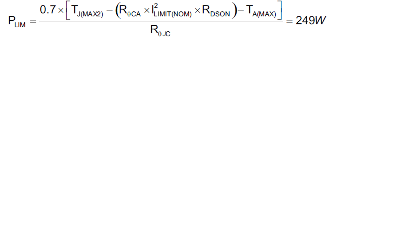
prevent the M1 die temperature from exceeding a short term maximum temperature, TJ(MAX2). Short term TJ(MAX2) may be set as high as 150°C (specified on FET datasheet) while still leaving ample margin for the typical manufacturer's rating of 175°C. The R4 and R5 resistors set VPROG, programming the FET power dissipation. Assume that RθJA is 10 °C/W, RθJC is 0.2 °C/W, and RθCA is 9.8 °C/W for the device we chose above. PLIM can be estimated as follows:
Where RθCA is the M1 plus PCB case-to-ambient thermal resistance, RθJC is M1 junction-to-case thermal resistance, RDSON is M1 channel resistance at the maximum operating temperature, and the factor of 0.7 accounts for the tolerance of the constant power engine. In this case we know that power limit is less than ILIMIT x VIN and that power limit will control operation during a short circuit.