This thread has been locked.

If you have a related question, please click the "Ask a related question" button in the top right corner. The newly created question will be automatically linked to this question.

TPS4H160-Q1: Schematic check and funny current limit behavior

Part Number: TPS4H160-Q1

Hi guys,

My customer designed in this high side switch and is having trouble with the parts overcurrent regulation. There are two cases and two schematic below, where one case operated as expected and the other did not:

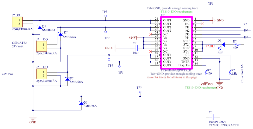
Case 1: 2.8K Resistor was set for current limit of 0.6A but it did regulation/protection at 0.9A.

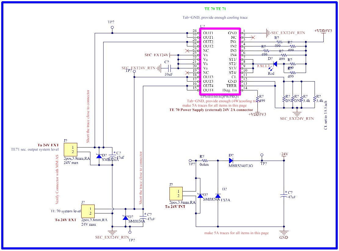
Case 2:  1.7K Resistor was set for current limit of 1A and  it did regulation/protection at ~1A.


I am not sure why in case 1 it didn’t go good job of accurate limit but it did in second case.

RL [Ω]

IRL [A]

VRL [V]

RCL [kΩ]

(set for 0.6A)

Mode

Time [min]

StS O/P [V]

Device Temp. [⁰C]

NA

0.6

23.80

2.8

Ind. Config.

NA

NA-VerB

NA

NA

0.7

23.76

2.8

Ind. Config.

NA

NA-VerB

NA

(29.65)

0.8

23.72

2.8

Ind. Config.

10min

NA-VerB

28.0

NA

Drop from 0.9 to 0

23.40

2.8

Ind. Config.

NA

NA-VerB

NA

0(short)

0A

0.03V

2.8

Ind. Config.

NA

NA-VerB

NA


Thanks,

Brian 

  • Hello,

    Both schematics looks OK.
    The nominal current limit level is 0.8V x 2500/Rcl.
    If RcL = 2.8K, the nominal current limit is 714mA. By counting the current ratio tolerance of 15% , 607mA < current limit < 821mA.
    If RcL = 1.7K, the nominal current limit is 1176mA. By counting the current ratio tolerance of 15% , 1000mA < current limit < 1353mA.
    The above calculation is without Rcl tolerance and has to be added.
    The current ratio tolerance is better with higher current limit set.
    How you measure the current? are you using high accuracy current probe?
    I can see in the second schematic, paralleling 2 channels. Is the total current measured and divided by 2?
    Are you sure in both schematics the current hits the limit and and FET is in saturation region?
    Would you please send scope pictures including load current and output voltage?

    Regards
  • Here are the responses:

    Both schematics looks OK.
    The nominal current limit level is 0.8V x 2500/Rcl.
    If RcL = 2.8K, the nominal current limit is 714mA. By counting the current ratio tolerance of 15% , 607mA < current limit < 821mA.
    If RcL = 1.7K, the nominal current limit is 1176mA. By counting the current ratio tolerance of 15% , 1000mA < current limit < 1353mA.
    The above calculation is without Rcl tolerance and has to be added. We used 1% tolerance resistances. Which makes it 16% overall tolerance.
    The current ratio tolerance is better with higher current limit set.

    • How you measure the current? are you using high accuracy current probe? < we used Fluke DMM to read current (series connection). Fluke has less than 1% error.
    • I can see in the second schematic, paralleling 2 channels. Is the total current measured and divided by 2? Actually we measured combined current which limited itself to 2A. in result below I have divided that # by factor of two.
    • Are you sure in both schematics the current hits the limit and and FET is in saturation region? < Not sure, how can we ensure, I didn’t see any saturation vale in datasheet.
    • Would you please send scope pictures including load current and output voltage? <sure in our next try we will capture this.


    Thanks,

    Brian 

  • Mahmoud,

    I checked in with my customer about the scopeshots, sounds like they have a backed up lab and aren't sure when they can get in to collect them. in the meantime, can you add some color to these items from my above post?

    • Are you sure in both schematics the current hits the limit and and FET is in saturation region? < Not sure, how can we ensure, I didn’t see any saturation value in datasheet.
    • I felt it strange that on same setup 1.7K configuration did current limit on lower side of 15% and other configuration did it on higher side of 15%.

    Thanks,
    Brian
  • Hello Brian,

    1- Saturation region means drain to source voltage is higher than On-resistance x load current.

    2- I think there is an issue on the parallelked channels configuration. Is that right? please check SLVA949 document about paralleling channels. There are more tolerances to be considered when paralleng channels.

    Regards