This thread has been locked.

If you have a related question, please click the "Ask a related question" button in the top right corner. The newly created question will be automatically linked to this question.

TPS2114: Current Limit Not Working

Part Number: TPS2114
Other Parts Discussed in Thread: TPS2115, TPS2113A, TPS2113,

Hi, I hope someone can help me.

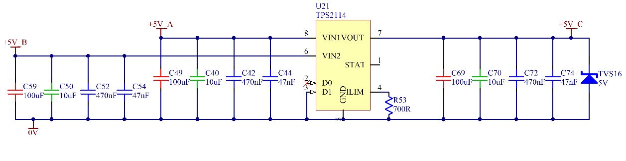
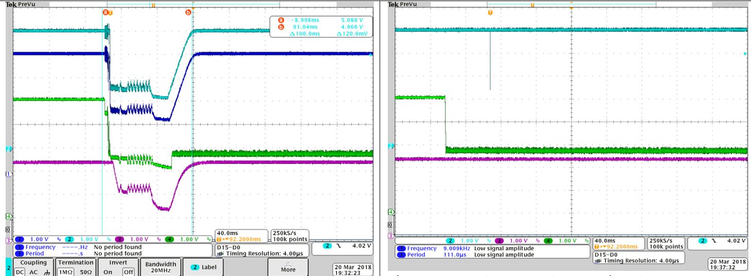
We use the TPS2114APW in several products to OR together two 5V supplies and provide current limiting. We’ve found that under certain circumstances the current limiting either doesn’t work at all or current limits at a much higher current.

We only see this problem sometimes when the input supplies are at a similar voltage and the output of the TPS2114 is suddenly loaded beyond the current limit. We don’t see this loss of current limit if one supply is 3V and the other is 5V for example, only when both are at 5V.

Thanks in advance

Gordon

  • Hi Gordon,

    When you say the current limit is not working, are you able to pass more current through the device than expected? Do you have any scope shots or data to show the problem you are seeing? Also, can you share your schematic so that I can see how the device is configured?

    Thanks,

    Alek Kaknevicius

  • Hi Alek,

    This only happens sometimes.

    It looks like the TPS2114 has either a much higher current limit (say twice or three times or more, I haven't tried to measure it) when the output is shorted.

    As a test I have run the 2 inputs from power supplies and both supplies current limit at the same time, each indicating over double what the TPS2114 was set to with R lim. I've tried with different current limit setting resistors and I can still make it fault in a similar manner.

    When the current limit works correctly, a short on the TPS2114 output is fine. The TPS2114 limits the current to the correct value and the output collapses as it should. The upstream supplies are fine. One indicates zero current and the other indicates the TPS2114 output current.

    Thanks

    Gordon

  • Hi Alek

    I have got some waveforms to look at. The circuit is that shown above. 5V_A and 5V_B are provided from bench supplies.

    The green trace in the first picture is the output from the TPS2114. It is suddenly loaded though not enough to collapse it completely. The blue traces show the voltages on the TPS2114 IN1 and IN2 inputs. Both inputs sag as they are current limited further upstream (circuit details not shown). This is the fault condition.

    The second picture shows what happens when IN1 is 5V and IN2 is 0V. The same load on the output of the TPS2114 is fine. The TPS2114 current limits as it should and the IN1 stays up.

    Hope this helps

    Regards

    Gordon

  • Hi Gordon,

    Apologies for the delay in reply.

    This is pretty strange behavior, especially when the TPS2114 has no problem. It looks like the current load on IN1 causes a voltage drop, and then IN2 > IN1, so IN2 takes over for the output. Then IN1 recovers and it keeps switching back and forth. This is because both sources are 5V and even a small voltage drop can cause a switch in supply. Perhaps the current is not able to get high enough to trip the limit because both sources are switching before the current can reach the current limit.

    Are both the TPS2114 and TPS2115 set to the same current limit?

    Thanks,

    Alek Kaknevicius

  • Hi Alek,

    Why do you say the TPS2114 has no problem?

    I agree with your summary about the supplies switching back and forth but I'm thinking it might be that the TPS2114 current limit is disabled momentarily when switching between IN1 and IN2 and if the switching occurs repeatedly then there is no effective current limit at all.

    We are not using the TPS2115. We only use the TPS2114 and the current limit is set via the single current limit setting resistor.

    Regards

    Gordon

  • Hi Gordon,

    My mistake, I misread the information you provided and thought the first scope shot was TPS2115. With both of them being TPS2114, I think your summary may be correct. To be sure, would you be able to check with IN1=5V and IN2=4.5V? That way we can confirm that it is not just both channels being powered, it is that both channels are the same voltage.

    Thanks,

    Alek Kaknevicius

  • Hi Alek

    I have checked the TPS2114 with IN1 at 5V and IN2 at 4.5V and again with the opposite voltages on IN1 and IN2. The TPS2114 current limits perfectly according to the limits set by the current limiting resistor. Yet if I set both voltages the same I can get it to fault (not every time but often enough to observe).

    Thanks

    Regards

    Gordon

  • Hi Gordon,

    It sounds like this may be the issue then. We do have another device, the TPS2113A, that can be configured to switchover at a specified voltage threshold instead of a voltage difference between sources. Page 16 of the datasheet has more information (figure 14). Do you think this device may work in your application?

    Thanks,

    Alek Kaknevicius

  • Hi Alek

    Can you suggest a workaround for the TPS2114?

    The TPS2113 is not pin compatible so it means changing several PCB's as we use the TPS2114 in a number of our products.

    Thanks

    Regards

    Gordon

  • Hi Gordon,

    Unfortunately, I am not sure that there is a way to come up with a workaround for the TPS2114 without changing the PCB. Maybe a higher capacitance on the input would cause the voltage source to dip less and allow the current to get high enough to trip, but I don't have a good idea of how high that capacitance would need to be. Other changes (including the TPS2113A) would likely require a layout change of some kind.

    Thanks,

    Alek Kaknevicius

  • Thanks for your help Alek,
    I have recently done tests with the TPS2113A (with the Vsense pin held below 0.8V so that it takes the higher of the two inputs just like the TPS2114A) and that seems to have the same loss of current limit when switching rapidly between the two supplies that I have seen on the TPS2114A.
    Getting more hysteresis by using a resistor divider on the TPS2113A Vsense pin doesn't fix the loss of current limit completely (it's much harder for me to get it to fault though) and it does require a change to the PCB which I'm unhappy about.
    This hasn't resolved my issue but I think you can probably close this thread.
    Thanks again
    Regards
    Gordon