Other Parts Discussed in Thread: BQ24171, BQ24160
Dear TI,
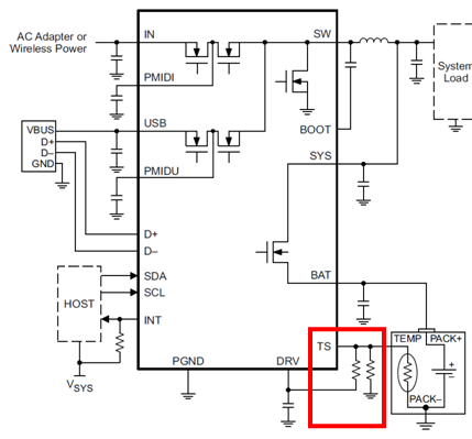
I'm using the Charger IC (BQ24160A) circuit as below. I would like to inquire about the TS pin.
It is not easy to understand, but there is an issue that if R83 resistance is arranged more than 10Kohm in the following circuit, it does not wake-up when battery protection (0V lock-up) occurs.
Our battery 3.0V ~ 4.2V, Single-cell 3050mAh is in use.
(Problems arise when the recommended values R83 = 12Kohm and R75 = 5.6Kohm from TI, The current state is as follows: R83 = 1Kohm)
1.inquire whether reference schematic around TS pin is available for each status.
< Battery temperature 0 ~ 60 degrees, 0 ~ 45 degrees >
How to set the resistance value of the red rectangle below to know how to perform charging in the above condition?
(The range of Thermistor inside our battery is 27.28kohm ~ 3.02kohm (0 ~ 60 degrees))
2. Question about the TS status related documents on the datasheet.
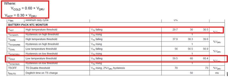
It seems that the following two calculation methods are different among TS setting between 0 ~ 60 degrees
Which of the following two calculation methods is the Vhot, Vcold voltage calculation method?
3. As with BQ24171, if you can provide a table of resistance values, please share for us.
(The example below is the calculation table provided when designing BQ24171)
thanks,
TS


