I'm designing a boost converter to drive an array of leds with the LM3421. The design is based on a previous version that is already in production but we need higher power and a different led fixture this time. Since the product will be used to illuminate high-speed video we need to use analog dimming. The design seems to work at higher power levels but at low power (high dimming ratio) we seem to be running into some weird stability issues. The problem appears as a low (relatively) frequency oscillation in output current. The frequency of this oscillation seems to go down with current - so as we dim more and more we eventually get the leds to blink at visible intervals (tens on Hz). This can be seen in the scope capture below - the yellow trace is output voltage, blue is main switching fet gate. It seems that for some reason switching stops and restarts periodically.
At startup there is one bigger peak but the waveform appears very fast and is very stable. The peak to peak amplitude and frequency seem to depend on the on-time of the main fet (and that depends on the relationship between input voltage and output current).
I know that this driver has a minimum on-time of around 200ns and I am trying to respect that but with the amount of jitter in the fet pulse length it is difficult. What might cause jitter in the pulse length?
Fet waveform at the minimum allowed length:
The problem becomes visible and bad when the pulse length jitter causes on-times shorter than 200ns.
Also there seems to be some bad oscillation at the turn-off of the main fet. Unfortunately the scope I have is ... sub-par ... so I'm not sure what exactly is happening there.
It looks like a lot of aliasing is going on in the ringing region but there must be something there for it to show up like this (I think). I'm not sure if this has anything to do with the periodic operation of the converter.
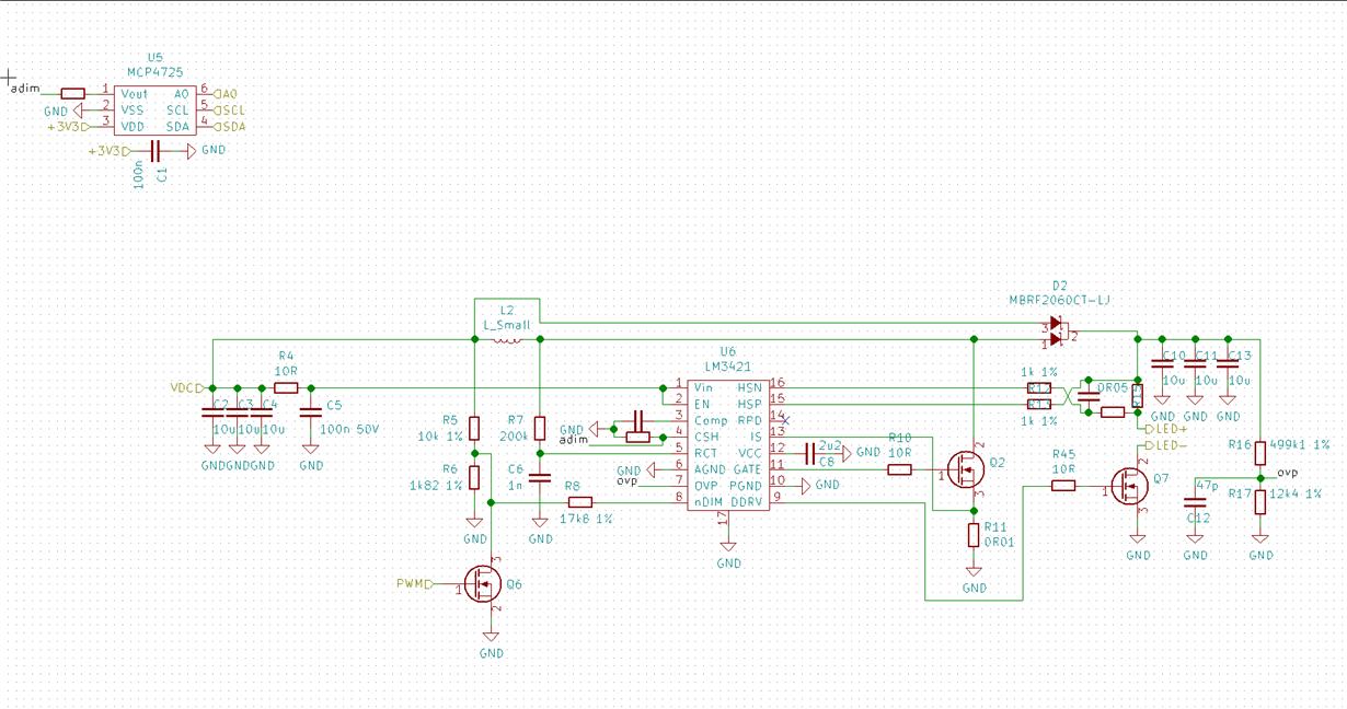
My main question is what could be causing the periodic operation? It kind of looks like a converter working in burst mode for a very light load (which this is for this design - the maximum output current is ~4 A, this problem appears at under some hundreds of milliamps) but as far as I can understand this converter shouldn't have a burst mode operating mode. The problem seems to exaggerated with noise on the CSH pin - these scope captures were taken with a large resistor soldered to the CSH pin to force the output current to be small. My schematic actually uses a 12 bit DAC to drive current into the CSH pin resistor to enable controllable dimming.
This is the schematic I have now.
To test without current control I just removed the resistor from the DAC output and increased the CSH resistor from 12k4 to 570k. This set the output current to ~20mA. With the DAC connected the problem appears sooner - even at ~500mA of output current.
We need to have as wide a dimming range as possible because we have two converters driving two white leds at 2700K and 6200K and we need to mix the colors and at low output at 6000K for example we need a tiny amount of 2700K to bring down the 6200K side. If the minimum current is too large our dimming range will be too restricted. I have implemented PWM dimming in hardware as well but I'm not sure if it would help us here.


