Hello,
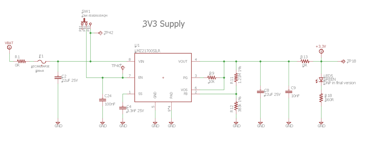
I am working on a design that uses a LMZ21700 to produce a 3.3V supply voltage from an 11.1V li/po battery pack. The previous revision of the design had the EN pin of the LMZ21700 connected directly to VIN at all times, so the regulator would be powered as long as a valid voltage input was supplied. This worked fine throughout all of the testing. The latest revision of the design, however, uses a JS102011SAQN SPDT slide switch as an on/off switch, where VIN is shorted to EN to turn the regulator on and EN is open-circuited (and pulled to GND through the EN pin's internal pull-down resistor).
Here is the schematic for the latest revision of the 3.3V supply:
This design has not been working as expected when testing the new PCB with this circuit.
Testing procedure with PCB 1:
- I started with the on/off switch SW1 in its default OFF position, to have EN internally pulled to GND.
- I supply power to the VBAT connection, and there is no voltage output as expected since the regulator is off.
- I then remove the VBAT power supply, switch the SW1 to the ON position, reconnect the power supply and expect to see 3.3V, but there is no 3.3V; instead, all I see is ~172mV DC output from the regulator. I've powered the board up again many times but the regulator does not seem to respond to either switch position now.
On a second PCB (one that was never used before), and I tested again using the following steps:
- Before powering the VBAT connection, I instead switched SW1 to its ON position (pins 2/3 shorted) to verify that the regulator worked initially. I powered the VBAT connection, and the 3.3V supply worked perfectly. While the board was still powered, I switched SW1 to its OFF position to check that the regulator would transition to the OFF state and nothing happened, the 3.3V continued to be outputted.
- I then removed the VBAT power source, connected a 1k pull-down resistor to pin-1 of SW1, just in case the internal pull-down resistor on the EN pin was not strong enough
- I then switched SW1 to its ON position again, powered the board, and 3.3V outputted fine, then switched SW1 it to the OFF position, and the regulator finally turned off.
- To see if the switch would consistently turn the regulator on/off, I switched SW1 ON, then OFF, then back ON, with ~5 seconds in between each switch position change. After ~2 seconds of running ON, the regulator's 3.3V output suddenly turned off. Similarly to the first PCB, this PCB now only outputs ~172mV DC when turned on.
I would like to know if anyone has had a similar issue with the EN pin on the LMZ21700 before, or if anyone has suggestions on why this issue is occurring or how to fix it.
Thank you,
Nicholas


