This thread has been locked.

If you have a related question, please click the "Ask a related question" button in the top right corner. The newly created question will be automatically linked to this question.

UCC28950: free wheeling period current through secondary rectifier diodes.

Part Number: UCC28950

hello

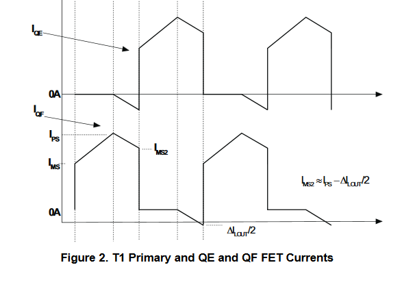
In SLUA560C equation no 14. circulating current when both QE and QF both on is calculated. so how is it? are both MOSFETS are carrying same current? why one is shown to carry negative current in figure 2 and whose magnitude is very small?

In relation to same free wheeling time, in TI.com/powertopologies chapter no 18. phase shifted full bride converter, page 188. why is that both the diodes are not shown conducting during freewheeling period? how these rectifier diodes behave in freewheeling period?

looking to understand operation of the secondary diodes especially,( not using synchronous rectification ) in condition when only top two  MOSFET switches are on. 

thanks in an

samrat

  • Hello Samrat

    The rectifiers - whether SR or diode - carry equal currents but at different times depending on the transformer voltage. This is taken into account by the factor Dmax/2 in the equation. Dmax is Ton/T as measured on the primary. The secondaries conduct alternately so each of them sees Dmax/2.

    The negative current labelled Delta(Iout)/2 is present ONLY if you are using Synchronous rectifiers. At this time, both SRs are on. During the previous Ton interval the output inductor current will have been flowing in one of the two centre tapped secondaries with the other secondary carrying no current. During the freewheeling interval the output inductor current decreases as the inductor supplies current to the output. But, because both of the SRs are on and the primary is short circuited by either the top or bottom pair of MOSFETs there is no voltage available to drive the inductor current out of one secondary and into the other. The result is that the current flows asymmetrically in the transformer secondary. However, if you are using SRs, the CHANGE in output inductor current flows equally in the two secondaries - one secondary current starts at zero and goes negative the other secondary current starts at a high value and reduces at a slower rate than it would had there been no negative current in the other winding.

    This negative current does not flow if you are using diode rectification - the diodes prevent negative current flow. The current at the start of the freewheeling interval is in one of the two secondaries and there is no voltage available to force it to share equally. The change in inductor current flows only in one diode because it cannot flow as a negative current in the other diode.

    All of the above applies to a centre tapped secondary ONLY -

    Hopefully this is clear

    Regards
    Colin

  • hello Colin,

    Understood the fact that the current will be unsymmetrical in case of synchronous rectification. but diode rectification case as you have said ''The current at the start of the freewheeling interval is in one of the two secondaries and there is no voltage available to force it to share equally''.

    Is inductor voltage not available ?

    considering like this, In free wheeling period , output inductor voltage is reversed now, and is providing load..current is decreasing , but is it not
    that both the diodes are forward biased because of the negative inductor voltage? when both the diodes are conducting, why current is only flowing in one of the secondary diodes during freewheeling period?

    ''because both of the SRs are on and the primary is short circuited by either the top or bottom pair of MOSFETs there is no voltage available to drive the inductor current out of one secondary and into the other.'' is it applicable to DIODES also?

    thanks in anticipation colin

    samrat
  • Hi Samrat

    There is no voltage across the transformer secondary during the freewheeling interval because the primary of the transformer is short circuited by the MOSFETs - either the two high side MOSFETs or the two low side MOSFETs. The inductor voltage is clamped to the output voltage by the rectifiers. For the diode rectification case - you are correct that both diodes are initially forward biased but the difference is that at the beginning of the freewheeling interval one of them starts out carrying the full inductor current and the other starts out at zero current. As the freewheeling interval progresses, the diode which was initially carrying the inductor current sees its current reduce as the inductor current reduces. The current in the other diode would try to reduce, but its starting point is 0A and it becomes reverse biased.
    Where I said ''because both of the SRs are on and the primary is short circuited by either the top or bottom pair of MOSFETs there is no voltage available to drive the inductor current out of one secondary and into the other.'' is it applicable to DIODES also?
    I meant the primary MOSFETS - and the comment applies to both Diode and SR Rectification..

    If you send me your email I can send you a presentation where this is (I hope) explained a bit better than I can here.

    Regards
    Colin
  • hello colin

    i have messaged you my email id. It will be great to have that presentation.

    and yes I understood ''reducing"!!

    thanks for support
    samrat