Hello,
I'm working on the following project: LLC resonant converter with synchronous rectifivation, I'm using ' UCD7138 4-A and 6-A Single-Channel Synchronous-Rectifier Driver With Body-Diode '.
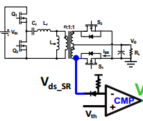
I'm looking for understanding the principle operation of bady diode detection and blanking signal.
Could you please help me by giving the complete diagram, something just like as the figure below demonstrates,and the maximum of explanations
Thank you
Best regards
H.EL KHAYYATY