This thread has been locked.

If you have a related question, please click the "Ask a related question" button in the top right corner. The newly created question will be automatically linked to this question.

TPS54302: IC getting damaged if touched by hand.

Part Number: TPS54302

We are testing TPS54302 for a new design and plan to implement it in more designs if performs well.

Input = 24V DC / 2A

Output: 3.3V / 2.5A

During the initial testing device was very stable at Heavy Load (2.5A) and Light Loads (200mA), with efficiency of 88-89%. The temperature on the IC and Input Capacitor was observed around 80C with and ambient of 27C. The temperature gets stabilized in 1-2 min of loading and then does not increase further. But we observed following issues:

1. If during operation the IC is touched by hand the output becomes unstable. We came across this situation while doing a quick temperature check of components. I am not sure why the IC becomes so unstable? Does it changes the frequency of operation?

2. While setting up device to check efficiency, the ammeter was connected with circuit in power-up condition (manually by hand). Apparently, IC did not like this and it got damaged (Output and Input became short). To confirm we did exactly the same one more time and again IC got damaged. Third time we connected the setup and then powered up the system and IC worked fine. Not sure why IC is getting damaged in such condition.

3. During testing of additional circuit (Temperature sensor LM87LP), we figured out that sensor was soldered incorrectly (Supply and GND pins were swapped). In this case also the TPS54302 got damaged.

Attaching the schematic for your reference, personally we like the IC for its form factor and efficiency, but it gets damaged again and hence we are not getting lot of confidence. I understand that we should not be touching operational components by hand but in field condition we will not have much control. In north India ESD is not of a factor, but even if that is a root cause then we want to know and make suitable provision for the same. Previously, we were using LM2596-ADJ, but form factor and commercials are not working out for that part so we want to replace it with small, efficient and cost effective solution.

Pretty sure we are missing something.

Please suggest.

  • It is possible that touching the IC you are affecting the FB pin.

    This may cause the output voltage to swing, but I am not sure about why the device would get damaged.

  • Touching does not damages the device, it causes the output to swing, yes FB may be getting effected. But never saw that happening on LM2596-ADJ.

    What causes the device to damage was variation in Input (connecting ammeter by hand in powered up condition) or in case of any short-circuit due to wrong connection of sensor at output. Not sure why it is getting damaged so frequently.
  • HI Mayank,

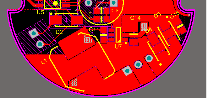
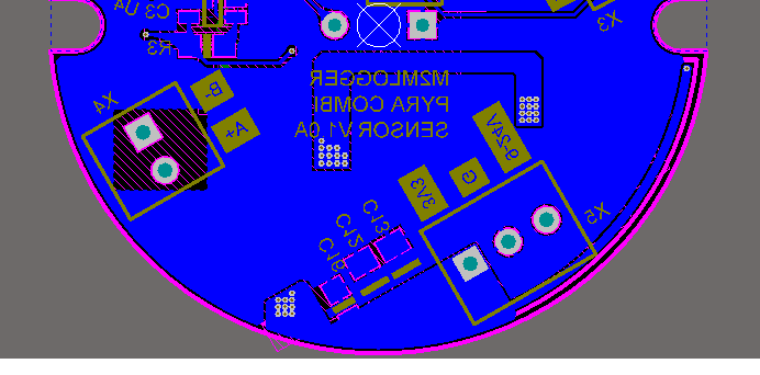
    The device should not be damaged in your condition. Could you share the layout and inductor datasheet? Have you captured any waveform of Vin and SW when you repeat the test for damage?
  • Hi Anthony,

    I have not captured any waveform as of now, but I can capture it and send across.

    Input Capacitor (C14): 10uF / 35V (Murata GRT31CR6YA106KE01L)

    Output Capacitor (C12, C13): 2 x 22uF / 16V X5R (Taiyo Yuden EMK316ABJ226ML-T)

    Inductor: 10uH, Idc: 4.3A, Isat: 5A  (Wurth 7447714100

    All the components are ordered from Genuine source i.e. Mouser and Wurth

  • Hi Anthony,

    Got chance to look into the PCB layout? Do you think placing a 47uF Electrolytic at power input will help minimize any noise entering the system?

  • Hi Mayank,

    For the layout, C15 is too far from the IC which make it less effective to shorten the high di/dt loop. And the GND plane connection also needs to improve. The input cap GND pad need to share the same polygon with the IC GND pin like the Vin pin polygon. Also, there should be some vias placed around IC GND pin and output cap GND pad.

    Another thing I would like to know is whether the input voltage 24V is stable or not. The input power supply should have steady 24V.
  • Thanks for the Revert Anthony,

    I will try to bring C15 closer to IC. However C14 is very nearby IC GND pin and is on same Ground plane as IC GND.

    Let me see how to add vias between output caps and IC GND. Do you think external SOLID ground connection will help?

    The Input supply 24V is stable, but I was reading somewhere that hot-plugging may create undesired spikes that could kill Switching Converter specially if it goes out of input range. Suggestion was to add bulk electrolytic Caps at input. Also the 26V TVS was not mounted on test board. Getting it all tested today.