Other Parts Discussed in Thread: LMX2572
Tool/software: WEBENCH® Design Tools
Hello,
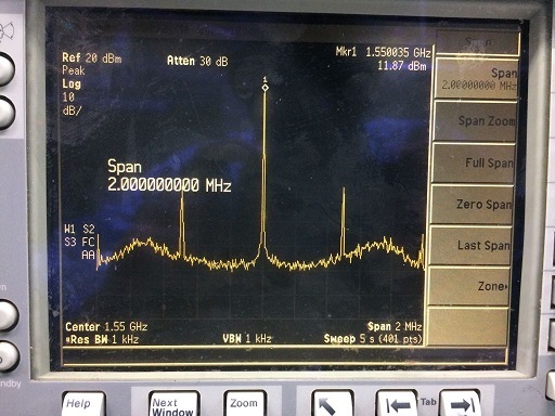
Iam new to Step down DC converters and can anybody can support me to solve the the spurious(refer below snap) generate in the LMX2572 RF output spectrum due to the LM43602 Step-down DC converter.
Iam using two stage step down for generate the required voltage for the LMX2572 PLL chip and initially the input +30V step down to +3.6V by using LM43602 and then it step-down to +3.3V by using TPS7A9101 LDO(refer below schematic).
Below are the requirement.
Input Voltage --> +30V
Required output voltage -->+3.3V/+1.8V
Output current -->0.2A@30V
Iam operating LM43602 part with default switching frequency of 500kHz(RT resistor open) below are the BOM which i had used.
Cin --> 4.7uF X 4 --> 18.8uF(total)
Lin --> 33uH(power inductor)
CBOOT --> 470nF
CFF --> 6.8pF(also tried with higher value of 36pF)
Cout-->22uF+47uF+10uF --> 79uF(total)
Lout --> 33uH(part# IHLP-3232DZ-11)
Css --> open
We had observed the spurious around the 500kHz offset which is same as the switching frequency of LM43602 and if we change the switching frequency by changing the RT res value the the spurious offset also moving as per that.
Could you please suggest optimum BOM values to eliminate the spurious issue and the requirement will be -75dBc with 50MHz span from the carrier of 1550MHz.
Can you suggest any ferried bead need to be used in between LM43602 & TPS7A910 to isolate the signal path and if so please suggest suitable part?
Looking forward your suggestions.
Regards,
RVP


