This thread has been locked.

If you have a related question, please click the "Ask a related question" button in the top right corner. The newly created question will be automatically linked to this question.

LM5122: lm5122 eval has issues, I have questions

Part Number: LM5122

hi, bought eval lm5122evm-2ph.  2 phases, nice board.

very confusing about the many  0 ohm resistors.  pads are on the board, some resistors are on the board, all resistors are in schematic, but not on BOM.  strange.

I take that back, that is confusing.  R22, R23, R30, R37, R18  0 ohm resistors are not in BOM, but are in schematic, all have pads (??), and some populated on board.

same issue with missing D3 diode and C33 cap.

normally, I don't care about errors in docs.  but designing my own LM5122 2PH board is difficult.  don't know if a part should be included or not.  can someone fix erros asap?

I manually laid out  my pcb this weekend, then saw 10-16 parts are zero ohms.  that's huuuuge.  I'm not putting 0 ohm resistors down on my pcb.  what a waste of time, I should have caught that.

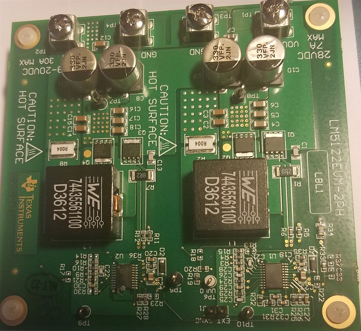
very alarming, is that populated C20 and R36 are reversed on the pcb.  this means the BST cap is not directly tied to BST pin--cap goes thru R36.  what is that all about?  don't say R36 is 0 ohms, what if a user changes the resistor--then all blows up?

more alarming is:

    1.  the STRONG mention of having Rg resistors for gate drive--necessary says the world, and says TI, ONsemi, etc.  but these on the board are all 0 ohms!!  explain!

    2.  mosfet gate pins MUST BE VERY CLOSE TO DRIVE OUTPUT PINS!  but this eval has 1.3" long traces.  way too long.  when I design a board, my mosfet gate pins are about 2-4mm away.

now that being said, when I have 2-4mm between driver and gate pin, do I need any Rg resistor?  I am using TI mosfets with 1.5 ohm internal Rg.  so adding external 1 ohm resistor, more than doubles time on & off, according to simulation.  please, only true honest-to-God experts replies.

  • Most 0 ohms are reserved positions so users can change to a different value if they want. For instance, you don't have to use a gate resistor, but we reserve a position so you can change to meet your performance requirement. Some 0 Ohms are actually jumpers used to configure the circuit. Users may want to slow down the gate drive to lower the EMI emission, but the drawback is reduced efficiency. You need to make trade offs in between based on your requirements.

    You can put MOSFET close to the IC, but it may not always be a case. As long as your gate and return traces are side by side, the MOSFET can be placed a further away. As you mentioned, being too close leaves not room for gate resistors, and leaving no option for your to change the drive speed. This doesn't mean it won't work or work worse. It just leaves no flexibility.

    Please not that the EVM is just an example and is optimized by the designer in his own opinion, which may not be perfect in others' opinion, but it works and works fine to its design spec.
  • xie xie for your reply.  understand about 0 ohm.

    my LO and HO trace length, no vias, is 5mm each.  can you please comment about how advantageous this short length is?

    can you get the docs fixed?  the BST cap & resistor on slave are wrong.  if I were you, and I was an Atmel Senior FAE, I would have replied:

    "thanks for the feedback, we'll fix the docs asap."

    eval may be just an example, but TI price is $150, a lot of money for "just an example".  components are not opinions, your LM5122 dictates what components to use.  the eval is confusing.

    I am marching ahead with my design.  actually excited about it.

  • Thank you for the feedback! :-)

    I am surprised by those non-documented components being installed on board. To help me resolve this issue faster, would you please take a EVM picture of each side (top and bottom) in good resolution, so I can read the silk screen and use the picture to discuss with our EVM designer?

    Again, thanks, and wish you good luck in your design.
  • hi, nice reply. I already pointed out which cap and resistor are exchanged. silk is correct. traces are wrong. you can simply look at TI's docs, and at your own eval board. no more questions until you answer mine.

    also, most resistors and caps are poorly laid out. look at top copper layer. the ground pads for most resistors and caps are all one block. this is confusing if trying to decipher connects. terrible design. each component should have its own ground pad, solder mask. not lumped into one big copper area. reason is initial soldering, and any rework, has to heat up the entire copper area, which is huuuge. this is serious, especially coupled with purpose of eval is to change parts. likely delamination of copper due to excessive heat applied to remove any part.
    this is enough for immediate dismissal.

    on scale of 0 to 10, this is a 0 board. TI never should have released this board. who is the manager who approved it?

    my question:
    my LO and HO trace length, no vias needed, is 5mm each. can you please comment about how advantageous this short length is?
    i.e. I absolutely do not need Rg external resistors, for my 1.5 ohm Rg internal mosfets?
  • Without your board picture, I have to order the EVM myself for a review. Also, I wish to see the forum be used to discuss and resolve issues but not for finger pointing anybody.

    Regarding your traces, short distance is always good. Note that the LM5122 has 3A strong driver and it may be too strong to drive your FET directly. If I were you, I would reserve a gate resistor position in case it is needed. Without it, you lose the flexibility and may have to do another PCB layout. The 1.5Ohm may not be enough. If you really hate to put a zero ohm resistor, I would suggest you to replace the EVM MOSFETs with your selected MOSFETs, and run some test to see if the switching performance is okay without external Rg.
  • hi, ok, I will gladly take pics for you. give me a day. but the exchanged cap and resistor is minor.

    thanks for your nice reply about Rg resistor. I understand. most, if not all LM5122 evals have 0 ohms Rg external.
    Therefore, since TI has sold hundreds, and no issues reported, at least to me, none in E2E forum, and you did not mention huge quantity of failures, no Rg resistor must be correct. that is enough proof for me.

    also, I have shipped 5,000 boards, each with 4 power mosfets (20K total) driven by FAN3227T (2A drivers), switching up to 15 amps each, 10A typ, NO Rg resistor. no failures due to no external Rg resistor.
    half of these were driven directly by mega328 pins, never a failure.

    google "do I need Rg mosfet resistor" and you will find enormous misconceived misapplied ideas. many answers were "can't hurt".

    well, it can hurt. 0 ohm resistor is not quite zero, plus trace length, counting going thru resistor, gets quite longer. the solder on the pads is a poor conductor, plus the resistor adds to inductance.

    what convinced me for sure, was a xls model by Zetex for driving power mosfets. it showed even 0.5 ohms Rg doubled my mosfet on/off times. 1 ohm almost tripled on/off.

    after designing for 45 years, I wanted to absolutely confirm no Rg is best. that's why I asked you, top TI expert!
  •  pics for you.  now I notice D3 & D4 are unpopulated, on bottom.  terrible!  there's enough room on top.  I want to have schottky diodes on my design.  don't worry, I won't make the mistake TI did, I'll put them on top.

  • error--can only insert 1 file per reply, fix this. pics for you. now I notice D3 & D4 are unpopulated, on bottom. terrible! there's enough room on top. I want to have schottky diodes on my design. don't worry, I won't make the mistake TI did, I'll put them on top.
  • thank you for the picture. Let me get the clarification from you: I don't see R22, R23, R30 and R18 are populated. Have you removed these resistors from the original EVM?
  • please pay attention, I wrote they are missing from bom. that is terrible. I have not touched the eval board yet.
  • Okay, its clear now.  Thanks for the confirmation.