


Other Parts Discussed in Thread: TPS25942A, TPS24751
I have implemented a circuit similar to some of the other posts on this forum, with Rset = 49.9k for maximum current, and with a timing capacitance of 10uF for a fault time of 400ms. The device is implemented as a button controlled load switch. The button circuit is functioning properly, and is not causing any issue with enable control. The switch connects a lithium ion battery stack to a load consisting of voltage regulators and an additional downstream load.
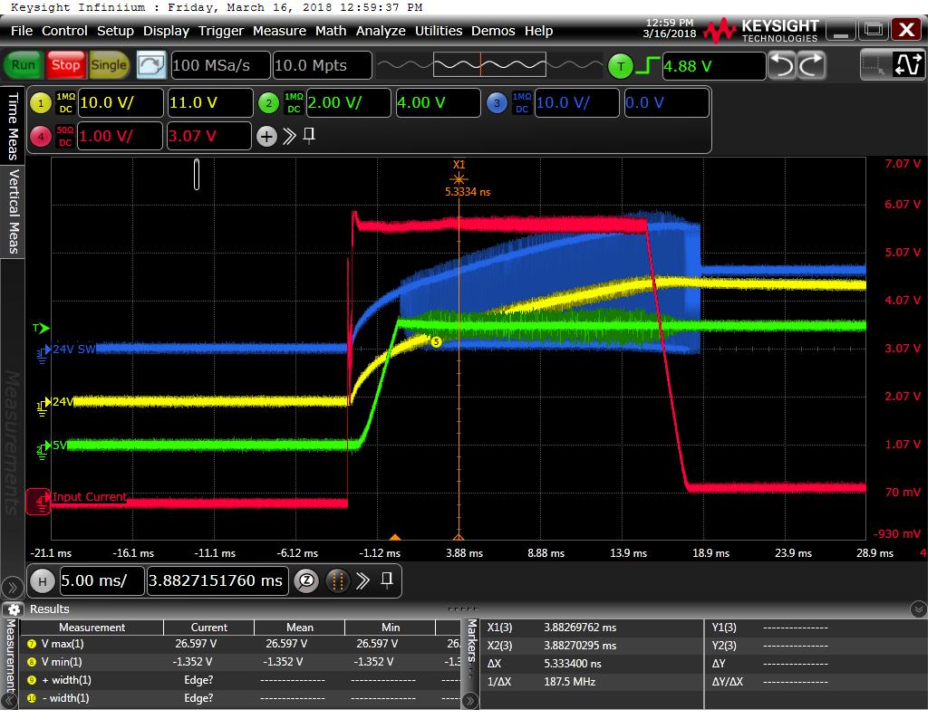
Before implementing the switch the load startup even was measured and characterized in the following plot. Note that the maximum inrush current is 5.5A at Vin = 16.8V, and the inrush even lasts about 20ms. Load current is the red waveform, and the others are voltages at the outputs of the regulators.
When implemented with the TPS2421, the circuit is not working. It appears something is internally limiting the output current to 700mA and tripping the fault timer. I have been unable to get the circuit to start up successfully with a load attached to the power supply, but if I remove the load and just start up the power supply, it successfully starts up. This can be seen below. Note that the below graph does NOT depict the fully loaded system.

The load that is not present in the plot above has a large capacitance (~4.5mF), that should be adequately charged at the rated current for this device. I selected this IC for this application because it is capable of handling large transient currents, so I am not sure why I am seeing this result. Even with the large capacitive load removed, the TPS2421 appears to be limiting the input current.
Any insight is appreciated.
Thanks,
Sean