This thread has been locked.

If you have a related question, please click the "Ask a related question" button in the top right corner. The newly created question will be automatically linked to this question.

BQ76940EVM: Schematic TIDA-00792

Part Number: BQ76940EVM
Other Parts Discussed in Thread: TIDA-00792, BQ76940

Hi ,

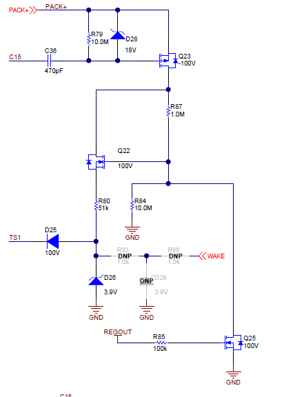
Please explain the below circuit. Schematic TIDA-00792 (page 2)

1) How the Q23 will turn ON? Pack+ will be always ruining voltage so the same voltage will flow through R79 and Q23 doesn't  get turn ON.

2) How much the Pack voltage will flow through R79? Pack depends on our total cell voltage? e.i. (for 13 cells )4.2V x13 cells 54.6V, 54.6V will flow through R79? or only single cell voltage ll flow ? 4.2V

-------------------------------

Design 2

Can i use below circuit for my project?

in this circuit i am controlling Mosfet through MCU

kindly reply

  • Hi,

    1. It is boot circuit from charger when Pack+ drops to 0. If Pack+ voltage stays high, Q23 can't be turned on.
    2. If Pack+ is not dropped, no voltage drop happens
    3. It will turn on the Q22 when Enable is high enough.
  • Hi,
    Q23 never get turn. Because (charger)pack+ and (battery)BATT+ are same connection IF we check in bq76940 evm
  • Hi Rajaneesh,
    1. This circuit does not work with the EVM which has low side switching. This circuit is designed for high side switching such as the TIDA-00792. When the bq76940 is off and PACK+ falls to ~ 0V, C36 charges to a high voltage. When PACK+ rises by attaching a charger, the Q23 gate is held low by C36 while the source rises turning it on momentarily. Once PACK+ stabilizes and C36 discharges, it is off again. If PACK+ rises too slowly it will not work. See the waveform in the TIDA guide although there is not much detail. If PACK+ is held at the same voltage as the battery it will not work. For boot signal ideas with low side switching, see the application note in the bq76940 product folder.

    2. Yes your circuit should work. The continuous current through R is sometimes undesired in a battery application, be sure to keep the R large to minimize that current.