This thread has been locked.

If you have a related question, please click the "Ask a related question" button in the top right corner. The newly created question will be automatically linked to this question.

UCC28070: Input current spikes at heavy loads

Part Number: UCC28070
Dear Gentlmen:
         I am using UCC28070 to complete a 6.6KW OBC project,Output voltage is set to 403V,Frequency:100KHZ,Dmax:0.85,L=210uH
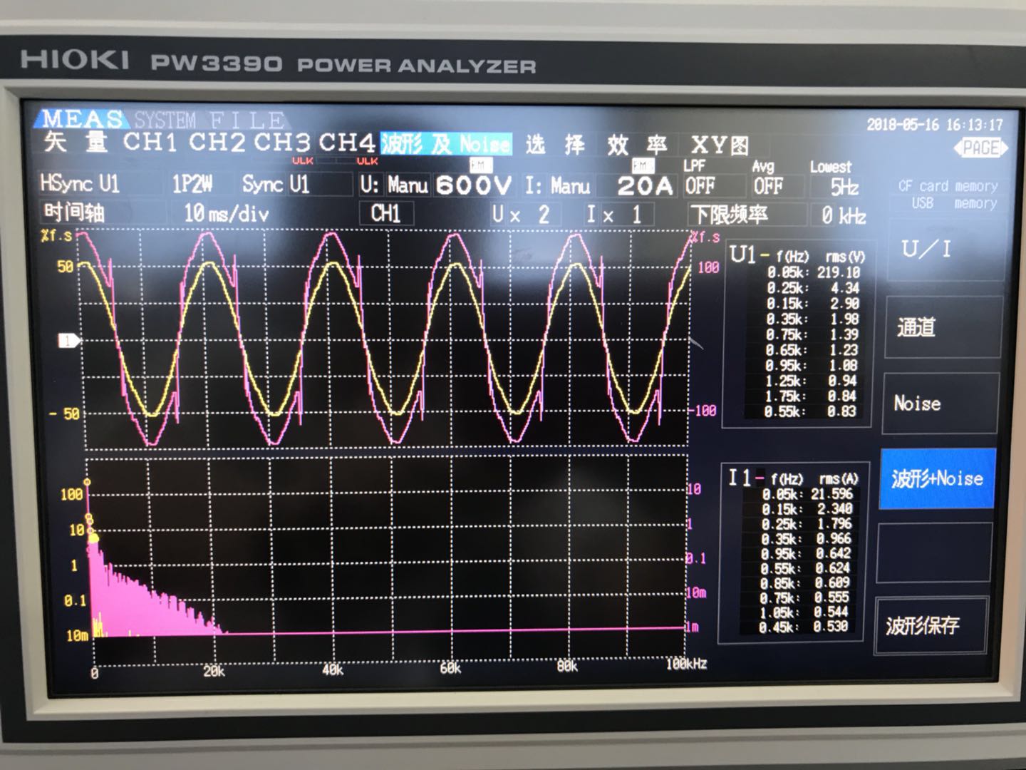
         When the input voltage is 220Vac and the output power exceeds 4400W, there will be a large spike in the input current. At this time, the PF will decrease sharply, and the waveform is shown in the figure. What is the reason?Test waveform.docx
  • Hello,
    Your waveform shows the spikes around the zero crossing and I think it would be useful to get some more detailed waveforms.
    Can you get a scope shot showing the gate drive duty cycle, current amplifier output and the current amplifier input.

    The duty cycle is at its max value around the zero crossings and Dmax = 0.85 is a relatively low value.
    If the current amp were saturating you could expect to see some spikes here associated with the delay in the amp coming out of saturation
    So please
    (1) Take more detailed scope plots as described above
    (2) Try increasing the value of Dmax

    If you want to send me the schematic you can email johngriffin@ti.com and I will gladly review and provide more suggestions
    Regards
    John
  • Dear John Griffin:

             thank you for your reply~

             According to your suggestion,I set the maximum duty cycle to 0.9 and, at the same time,I tested the IMO, VAO, and VINAC pin waveforms.Maybe You Are Right,According to my setup, the linear multiplier may have saturated, I tried to modify R88 to 17.4kohm, but the MOSFET break after hundreds of milliseconds without load, which is another problem.

             The problem is that the MOSFET is often damaged within a few hundred milliseconds after the run command is issued. Is there a timing requirement for the UCC28070 to power up or down?

              My machine is damaged and the waveform is sent to you later. Schematic diagram has been sent to your mailbox, please help review, thank you very much~

  • Hi,
    I ran the calculator tool with the data you emailed me and I notice:
    (1) The calculator recommends a burden resistor of 5.4 Ohms and your schematic uses 18 Ohms.
    This will cause the CSA/CSB inputs to saturate before the peak current is sensed.
    (2) The value of RIMO(R88) is recommended to be 115kOhms
    (3) also check the value of RSYNTH (R*() if you know the no load inductance of L2 and L3)
    (4) I would remove the compensating ramp from the CSA and CSB signals just to get the system running.
    You can always add it later and see if it helps.
    Remove D24 and D25
    (5) There is only 0.1uF decoupling on VCC pin. Please use 1uF ceramic on C61
    (6) C3 = 1uF and this is very low for a 6.6kW pfc
    I would recommend that you increase this value to about 3uF
    Please makes these recommended changes to the circuit.
    Then run your unit at reduced power and view the switching current on a scope.
    If all looks well, increase the power level up to 6.6kW
    Good luck !
    Regards
    John
  • Dear John Griffin:
    thank you for your reply~
    Is your calculator tool "UCC28070 Design Tool 8 15 08"?
    (1)Because the input current is limited to 30A, that is, when the input voltage is 85Vac, assuming that the efficiency is 1, the output power is only 2550W.5.4 Ohms should be the result of your calculation based on 6.6KW? Or should I calculate according to 6.6KW?
    (2)Same as above
    (6)C3 has been changed to 4.7uF
  • Hi,
    The Excel calculator is based here:
    www.ti.com/.../getliterature.tsp

    You should set the power rating of the pfc to whatever is your design requirements and make sure your supply can deliver this power at its rated voltage.

    Regards
    John
  • Hi

    Since there has been no posts for nearly 4 weeks I hope that you have solved your problem and I will close the post. If you have more questions pleas open a new post.

    Regards
    John