This thread has been locked.

If you have a related question, please click the "Ask a related question" button in the top right corner. The newly created question will be automatically linked to this question.

BQ34110EVM-796: Role of J3 in BQ34110 EVM

Part Number: BQ34110EVM-796
Other Parts Discussed in Thread: BQ34110, BQ77905, BQ7718

I'm trying to understand every detail of BQ34110 design based on the BQ34110 EVM. I still don't understand what J3 is used for. In the BQ34110 EVM user's guide (SLUUBI1), section 3.2.1 said that J3 is used to select the mode of operation, but doesn't explain any further. So I wonder which mode  is it about?

  • Hi Viet,

    J3 is included for customers that want to use the VEN/GPIO pin as a GPIO, so they can disconnect it from controlling the circuit containing Q2 & Q3. Ideally Q3 would have had a pulldown resistor on its gate to gnd. If you remove J3, you can tie the gate of Q3 to gnd to disable the FET (which also disables Q2).

    Thanks,

    Terry
  • Hi Terry,

    Thanks for the quick response. However my question is specifically what happens when I have VEN/GPIO control Q3 through J3 (connected). What happens when I have VEN/GPIO low and what happens when VEN/GPIO high?

    When it is high does it turn off the whole system, and vice versa when it is low then the system is on?
  • Hi Viet,

    When you are using the VEN pin for the voltage enable function (not for GPIO functionality), then VEN will be driven high while the gauge is measuring the voltage at BAT, and it will be driven low other times.

    The VEN controls a resistive divider to divide down the top-of-stack voltage and apply it to the BAT pin.  This could have been a simple resistive divider (without any FETs), but then it would draw current continuously.  So to reduce the power drawn from the stack, the circuitry of Q2 and Q3 is included - this causes the divider to only be powered while the gauge is measuring BAT, and it is powered off when it is not measuring.

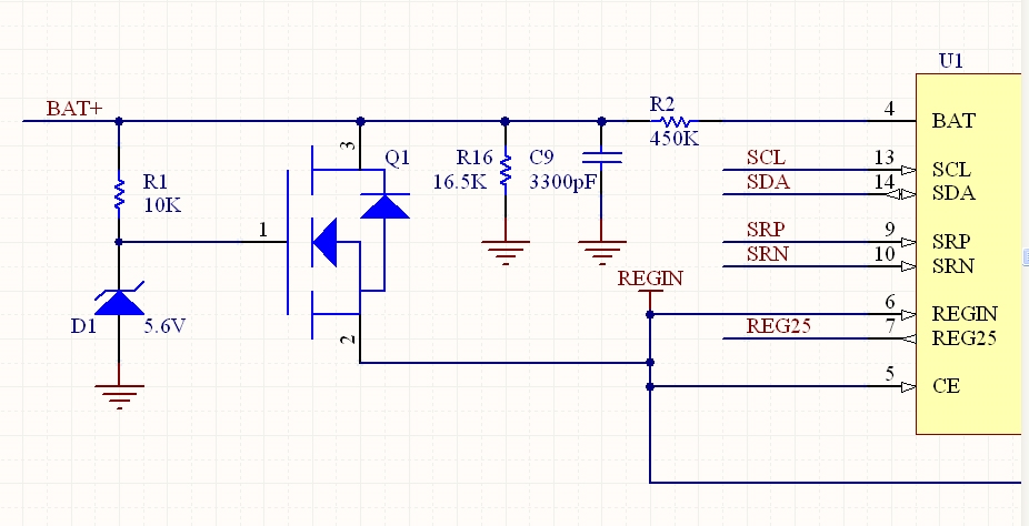
    The gauge itself gets its supply voltage from REGIN, this is powered continuously using the circuit consisting of D1, R1, Q1.

    When VEN is driven low, the divider is off.  Q3 is driven off, which means the gate of Q2 will be pulled high, causing Q2 to be turned off, and so no current flows through either branch.

    When VEN in driven high, the divider is on.  Q3 is driven on, so it causes the gate of Q2 to be pulled low enough to turn on Q2.  When Q2 is on, current flows through R9, R12, R13, and R8, dividing down the top-of-stack voltage to a level <1V, which is measured at the BAT pin.

    Thanks,

    Terry

  • Hi Terry,

    Thank you for the explanation. Just to confirm my understanding, if I leave J3 open,  then Q1 has open Gate, and it will continuously draw current?

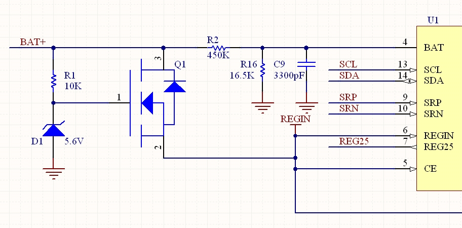
    If it is the case then can I simply remove Q2 and Q3, leaving just a resistor between BAT+ and the input BAT in BQ34110? I'm using multicell >5 configuration. The R2 resistor is 450K for a 24V battery voltage. The only drawback is that current is continuously flowing.if power consumption is not a critical factor. I'm enclosing the new simplified design.

  • Hi Viet,

    You have the R2 in the wrong position - you need to move it to the left of R16, so it is between the BAT+ 24V voltage and R16. That will implement the divider correctly, so the voltage that appears at the BAT pin will be <1V.

    Thanks,

    Terry
  • Hi Terry,

    Thanks for the suggestion. I moved R2 to the left now. We are just starting to design our own BQ34110 and we might go back to the original design with Q2 and Q3 when needed.

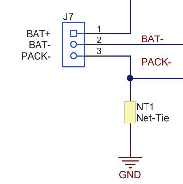
    Since you are so knowledgeable on this subject, I just want to have a quick and simple question instead of posting a new post. At the PACK- connector I see NT1 which is labeled NT1 Net-Tie. I don't see it anywhere in the BQ34110 EVM. I wonder what is that Net-Tie for? It's not even listed in the BOM.

  • Hi Viet,

    The net tie is just a schematic element that implements a short circuit between two nodes in a controlled manner. You can see an explanation of this on the Altium website at www.altium.com/.../((Creating Connectivity))_AD

    In this case, the net tie shorts PACK- to GND in the schematic.

    Thanks,

    Terry
  • Hi Terry,

    I got it. But then that brings up another issue: since both BAT- and PACK- are grounded, therefore SRP and SRN are both grounded, then it looks like SRP and SRN don't have any effect on BQ34110?

  • I mean SRP and SRN are both grounded through a 100 Ohm resistor.
  • Hi Viet,

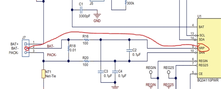
    I don't see what you are referring to - SRN is connected through R20 to GND=PACK-. SRP is connected through R16 to BAT-. BAT- is connected to PACK- through R18, which is the sense resistor. The voltage across R18 is what we are measuring with SRP & SRN. In the EVM schematic, R18 is 10mOhm, so for example, a 1A current through R18 will create a 10mV drop across that resistor, and this is what is measured by the device at SRP-SRN.

    Thanks,

    Terry
  • Hi Terry,

    Sorry I didn't include our actual design so you can see the problem I'm having.

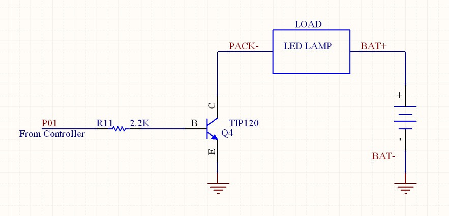
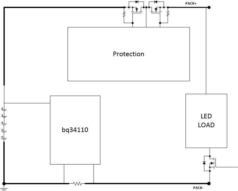
    As seen in this schematic, P01 is a GPIO from the controller. P01 is used to turn on/off Q4 which will turn on/off the load (LED Lamp). So in this case we have to connect BAT- to GND in order to make it work. Now I have to figure out how to connect BAT- and PACK- appropriately based on the BQ34110 EVM design.

    I would need your suggestion in this case.

    Thanks

  • Hi  Viet,

    That won't work properly with a gauge, the better configuration is:

  • Hi Terry,

    Thank you for the suggestion. I want to clarify and annotated your schematic and make sure it's correct.

    So in this case BAT- is tied to ground. We no longer want to have the Net-Tie. Now BAT- is going to SRN and PACK- is going to SRP.

    Something new here is the Protection circuit. Do we need another chip for the protection? Is there any example for the protection circuit by TI?

    Thanks.

  • Hi Viet,

    You need to reverse SRN and SRP (see below from EVM schematic).  Note that the VSS pin on the bq34110 should connect to BAT- gnd.

    Battery systems will generally always have some protection subsystem integrated.  This could be a circuit which controls FETs, which may be high-side, in the BAT+ to PACK+ line, or they may be low-side, in the BAT- to PACK- connection.

    The bq77905 is an option which supports low-side protection FETs, it can be stacked for higher cell counts.  This can be combined with bq76900 if you prefer high-side FETs.

    The bq7718 is another option for secondary protection, which can blow a chemical fuse to permanently disable the pack, if a serious issue is present.

    Thanks,


    Terry

  • Hi Terry,

    Thank you for all the explanation and suggestions about the BQ34110. I think I can move on with our design since this will probably be one product we will produce in very large quantity.

    You provided very great help and I hope we will have a good product using TI BQ34110.

    Regards.