This thread has been locked.

If you have a related question, please click the "Ask a related question" button in the top right corner. The newly created question will be automatically linked to this question.

BQ76940EVM: Schematic EVM,BQ79350

Part Number: BQ76940EVM
Other Parts Discussed in Thread: BQ78350, BQ78350-R1

Hi,

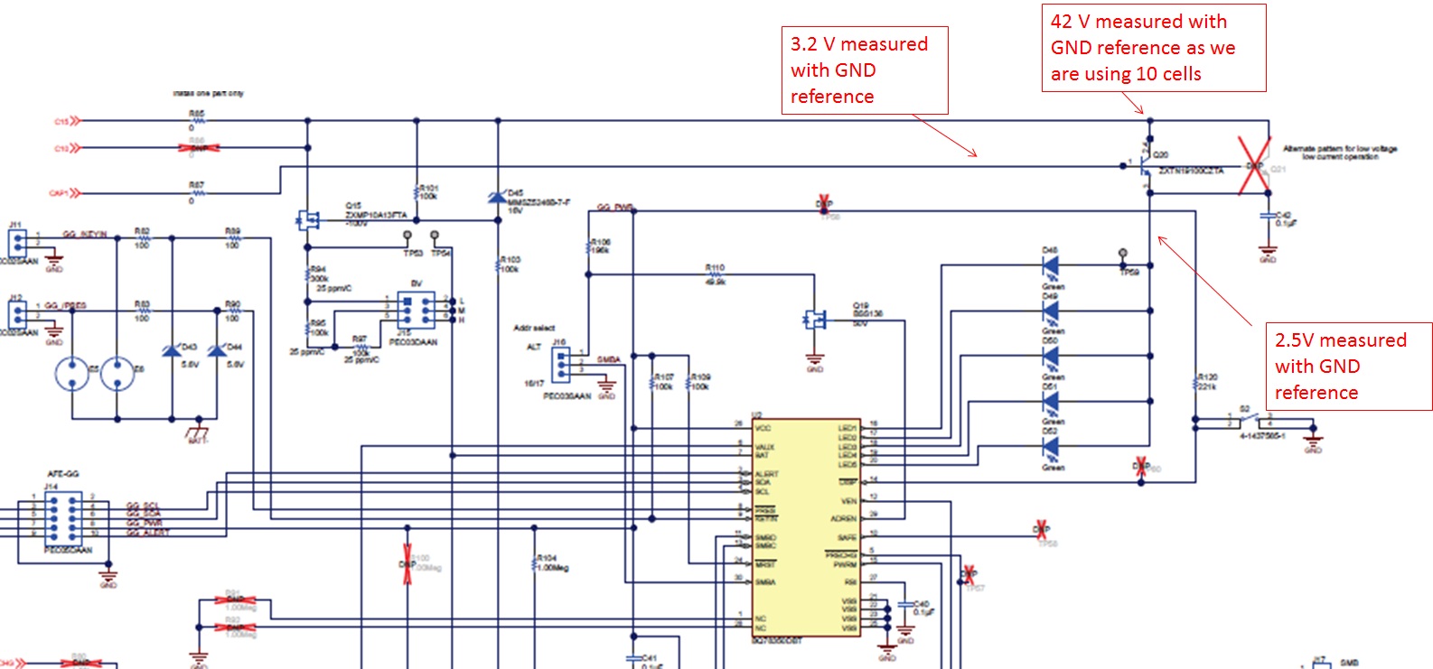
Please find the below attached image.Figure 36. bq76940EVM Schematic Diagram Gauge

I have measured voltage at  Q20 collector ,base,emitter. The voltage at collector is 42V with GND reference as we have connected 10S cells max voltage is 42V, thats fine and voltage at base is 3.1V its coming from the CAP1, measured with GND reference . but if we measure voltage at emitter then its 2.5V, measured with same GND reference.

how come the voltage at emitter is 2.5V  ?once the Q20 gets turn ON then, whatever voltage at collector its should flow to emitter excluding  diode drop.

i.e: Voltage at collector 42V  and emitter voltage should be 41.3V (0.7 diode drop normally)

1)why the 2.5V is coming in Q20 emitter?

2)BQ78350 has internal resistor for LED drive?(pin 16 to 20)

  • Hi Rajaneesh,
    Q20 operates as a "emitter follower" or "common collector amplifier". The emitter is about a diode drop below the base and current comes from the collector. Look up those terms in your favorite electronics text book or internet source for a better explanation.
    1) See above, the use of the emitter follower is to provide a high current source for the LEDs at a low voltage without using all the capability of the REGOUT supply. CAP1 is used as a reference since it is available, the current gain of the transistor should be high to minimize loading on CAP1.
    2) The bq78350 has current limited LED drivers, 3 mA nominal each. See the bq78350-R1 data sheet figure 4. Note that if the LED outputs are configured as GPIO outputs and set as open drain, they should not be used to drive LEDs without current limiting resistors. See the technical reference manual for configuration.