This thread has been locked.

If you have a related question, please click the "Ask a related question" button in the top right corner. The newly created question will be automatically linked to this question.

LP5907: Noise behavior idle vs 1 mA load

Part Number: LP5907

Hi team,

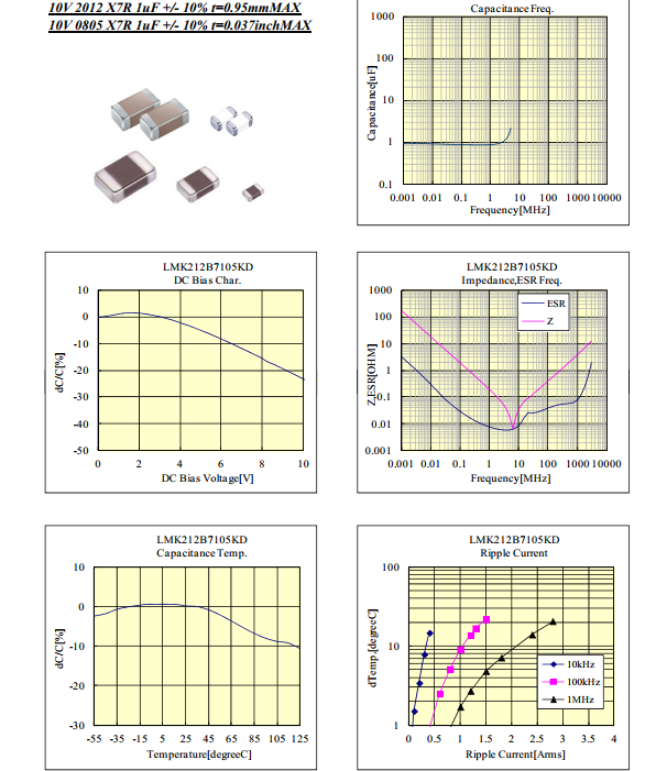
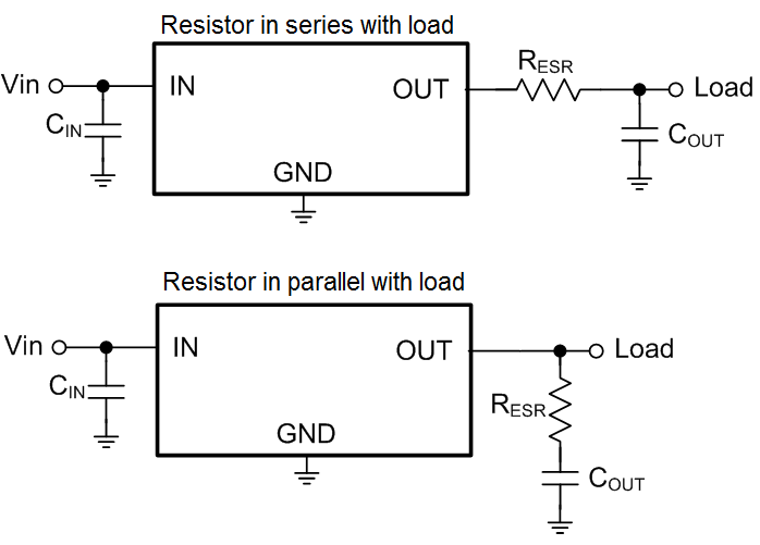
my customer is experiencing some phenomenon with a LP5907MFX-2.5. There is almost no DC load only some OPAMPs are connected a schematic is posted below: 

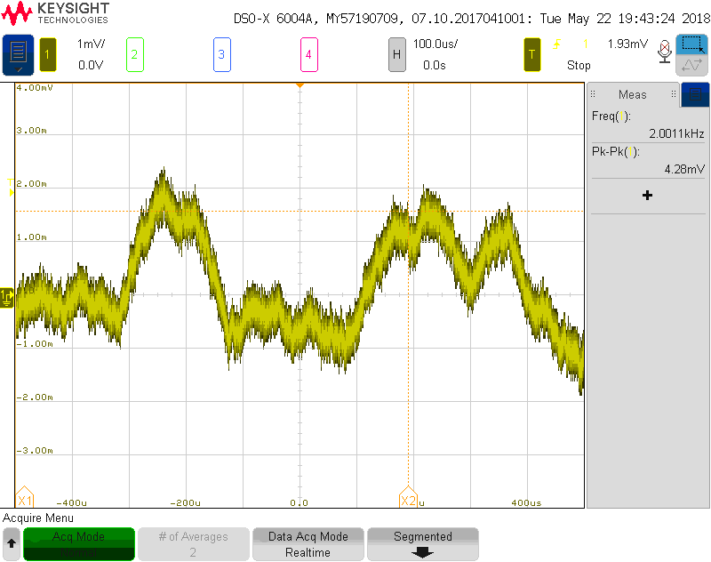
The requirement is that the 2.5 V are extremely quiet, especially harmonic signals of the sound spectrum should be avoided on the output. The customer is now experiencing some noise - artifacts of the used signal - on the 2.5 V output but only about 10 % of the LP5907MFX-2.5 show this behavior. The noise is in the region of 2 mVpp … 8 mVpp what is to high already.

The customer can not identify what in this 10% of cases triggers this event. The LP5907 itself, passive components or the OPAMP

At one board exchanging the LP5097 solved the problem, another board did not show any improvements after changing it.

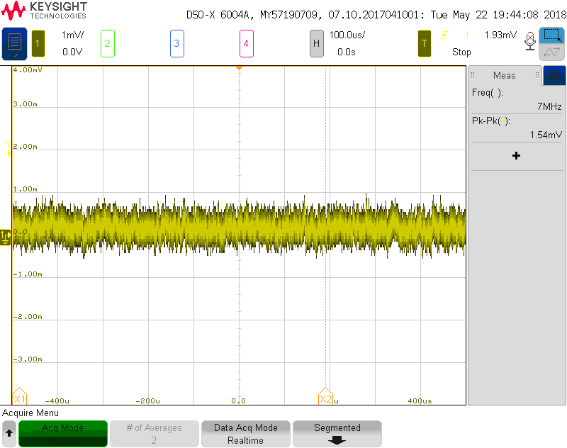
What definitively solved the problem is to force a small DC current of 1 mA by adding a load resistor. Now since the load regulation is speced from 1 mA the customer concludes this might be the explanation.

2.5 V without  load 

2.5 V with 1 mA load

Questions for you the experts:

  1. Is their conclusion correct: A base load is supporting the stability - and some devices of the LP5907 are more stable than others
  2. Would forcing this 1 mA current be a recommended solution for series production or should other effects be considered as well  

Kind regard 

Dierk

  • Hey Dierk,

    That is very strange. A minimum load shouldn't be needed, though some LDOs have less phase margin at very light loads. I see they have the minimum output cap, What is the voltage rating of that output capacitor? DC derating could cause there to be too little output capacitance. So between cap variance and LDO variance there could be some instability at low loads if the output capacitance is too low. They could try increasing the output capacitor (or using one with a higher voltage rating) to see if this helps.

    If they are ok with adding the constant current then there aren't any issues from the LDOs point of view.
  • Hi Dierk,

    several points come into my mind:

    1. Figure 17 of datasheet shows that load current changes can result in a certain noise modulation. But the effect should be only minimal and can hardly explain the noise of up to 8mVpp you observed.

    2. Providing a minimum load current can be very helpful for regulators. I remember that the good old LM78xx/79xx profited from a minimum load current of 5mA. This made sense as many parameters in their datasheets were specified for a load current of 5 mA <= IO <= 1A. Applied to the LP5907 which specifies many parameters for a load current of IOUT = 1 mA to 250 mA this would mean a minimum load current of 1mA.

    3. Section 8.2.2.6 of datasheet of LP5907 says:

    "The ESR of a typical 1 µF ceramic capacitor is in the range of 20 mΩ to 40 mΩ, which easily meets the ESR requirement for stability for the LP5907."

    Well, that's a bit out-of-date. Todays 1µ/X7R/0805 caps have somewhat lower ESR which can be even below 5mR. So, eventually, it could be helpful to put a 50m...100mR resistor in series to the 1µ/X7R/0805 cap to imitate a somewhat higher ESR.

    There's an additional pitfall: If there are more than one ceramic cap at the output of LP5907, they will appear to be in parallel, which can decrease the effective ESR furtherly. Is there another decoupling cap at the output of LP5907, eventually near the OPAmps? If so, you could isolate it by the introduce of a 1R series resistor.

    Kai
  • Hello colleagues,

    thanks for the quick response.

    The output cap is a Murata GRM188R71C105KA12D that has been carefully selected to maintain the LP5907's minimum requirement of .5µF under worst-case conditions. With the cap at minimum tolerance, DC-bias, ... it should never fall below .75µF. This also cannot be the explanation for the failing units, since the measured capacitances of the good and the bad units show no difference.

    We have tried varying the output capacitance using an additional ceramic cap of different magnitudes up to 47µF. At around 10µF we could observe a sawthooth-like periodic ripple of ~4mVpp at the LDO output, clearly caused by the LP5907 itself.

    Ignore the spikes in the oscillograph above - i used a long grund-tap at the probe to get my hands free.

    The base frequency of this oscillation decreases with rising output capacitance. So we decided to stay significantly lower than 10µF.

    An output capacitor in the range between 1µF...10µF did not held to suppress the signal artifacs as shown in the first picture.

    To clarify this: I am sure, that the problem here is not the oscillation of the LP5907. I can clearly recognize my signal waveforms on the 2V5 rail.

    There is a 100pF-coupled connection from the signal path to the P2V5-rail and i assume this is also the magnitude of the overall couplig capacitance from the signal path to 2V5.. The capacitive voltage divider 100pF/output-cap theoretically gives more than -80dB attenuation of the signal in the 2V5-rail.

    Adding another 2k2-Resistor in parallel to the output cap doesent explain the significant improvement shown in the second oscillograph.

    So my Question are:

    - How comes I see these signal artifacts at the P2V5 on some boards and only without the load resistor?

    - How comes, the load resistor eliminates this problem?

    - Will this load resistor solve the problem terminally?

    Maybe too low an ESR of the output capacitor is the problem here.There are 4 more 10nF caps in this net giving a pretty wideband low-Z shortcut in combination with the 1µF output cap.

    Maybe the answer is just too simple and I will smite my forehead right after stepping back for a day...

    Kind Regards,

    Jens (the customer)

  • Hi Jens,

    The picture you sent didn't come through, can you try again so we can see what is happening? Scope shots are one of the most helpful things that can be provided in most cases.

    You mention the signal coupling onto the power rail, if this coupling a is raising the voltage on the power rail (again I can't see the pic so I'm guessing here) then this could explain why the extra load current is helping. Typically LDOs do not have a way of pulling the output voltage down if it has gone too high and must rely on the load to do so. A higher DC load the faster the output voltage would reach it's regulation point.

    The LP5907 is only stable with 1uF-10uF on the output so it makes sense that the larger capacitors had problems. Also as you and alluded to the ESR of the output caps be too low. Most ceramic caps have an ESR of 5-10mOhms so with multiple caps in parallel that will be lower than the 5mOhm to 500mOhm range specified in the PDS.
  • Hello Kyle,

    of course! The LP5907 has no push-pull output. The additional burden discharges the output fast enough to keep the LDO regulating. *facepalm* :-)

    Concerning the output capacitor: Murata gives no useful specification of the ESR for the GRM-series, but as I just noticed, the selected component is about to be discontinued next year anyhow. So I will pick another Cap that has an ESR of at least 10mOhm or so.

    Just for interest: Would adding a resistive load be sufficient to compensate a rather too low ESR of the output cap in this given circuit (by means of adding phase margin)?

    Regards,

    Jens

    PS: I don't know why the image upload failed. I can add some more scope shots after returning to the bureau (on a business trip at the moment).

  • Hi Jens,

    it's always difficult to analyze a circuit without having a schematic...

    Taiyo Yuden has detailed datasheet which shows the ESR:

    Open the specsheet in the right of the page:

    Samsung has also nice datasheets.

    Take this ESR issue seriously. Adding a load resistor with so little impact on the load current will hardly cure a too low ESR. But you can easily add some resistance in series to the ceramic cap to imitate a higher ESR. I do this all the time in out circuits. Then even paralleling ceramics is fun.

    Kai

  • Hi Jens,

    No, adding the resistive load to account for a lack of ESR in Cout is not recommended as these two things are addressing separate problems. The cap ESR is addressing stability and your added resistive load is helping your application to discharge the noise coupling above your nominal output voltage.  

    Regarding ESR, murata actually has a good web tool for seeing the characteristics (impedance, ESR, voltage derating, etc...) of their caps and it has many GRM-series caps. You can find the ceramic caps here

    If the capacitor's ESR is too little then what is needed is an added resistor between the Vout pin and the output cap. There are two ways of doing this, adding a resistor so all the load current flows through that resistor (in series with the load) or adding a resistor so only the currently flowing into/out of the capacitor flows through that resistor (in parallel with the load).

    The series configuration works well for applications that have low load currents, multiple capacitors connected to Vout, or those which will have fast load transients. The series configuration doesn't limit the capacitor's ability to provide current during a load transient. 

    The parallel configuration works well for applications that have high load currents, minimal number of capacitors connect to Vout, or those that don't have stringent load transient requirements. The parallel configuration doesn't cause an I*R drop which can be problematic for higher loads. 

  • Hello guys,

    to conclude this thread:

    1.) The problem has been caused by the fact, that a capacitive coupling for an audio frequency signal onto the output of the linear regulator is present. Combined with a practically non-existent DC load, this lead measurable  to a signal remains at the LDO's output, since the LDO is not able to sink current and lower its output voltage under regulation. Adding an additional burden helps to discharge the output caps and keep the LDO in regulation. In this configuration we do not see any signal remains at the LDO's output rail, the noise behaviour is satisfying and we do not see any hints of instability.

    2.) The remarks concerning the ESR of the (output) caps are very good, nevertheless had nothing to do with the problem at hand. The ESR of the actual output capacitor configuration is at least 10mOhms, thus keeping the requirements for the LP5907. However, we will consider adding a low series resistor for the output cap when we are replacing the current caps in our next design loop.

    Thanks and best regards,

    Jens