This thread has been locked.

If you have a related question, please click the "Ask a related question" button in the top right corner. The newly created question will be automatically linked to this question.

BQ34Z100-G1: Problems configuring and calibrating gauge

Part Number: BQ34Z100-G1
Other Parts Discussed in Thread: BQSTUDIO,

We have an embedded system that works on a battery pack consisting of 4 cells (IFR26650, 3200 mAh, 3.2V), similar to these cells.
Our custom PCB contains a BQ34Z100PWR-G1 on a shared I2C bus, that can be accessed with the STM32 CPU we are using,
or directly by connecting an external connector to the I2C bus. The system must be turned on for this to work.

Circuit connection diagram
With Q1 an IRLML6402 and Q2 an IRLML6246.

We have an EV2300 and are trying to configure and calibrate the gauge with bqStudio so we can later flash an image directly to the
gauge or have the CPU configure it with the same settings through I2C (optional).

However, it's a bit unclear how some of the registry values must be configured to do a successful calibration.
Also, it seems that bqStudio is quite unreliable, since it often reports CRC check errors on read or write, or other 'unknown errors'
when trying to calibrate. If it auto-detects the gauge in the first place... Selecting the gauge from the list claims that it's not compatible'.

I am using the most recent stable build from the website (v1.3.54.1 from July 2017).

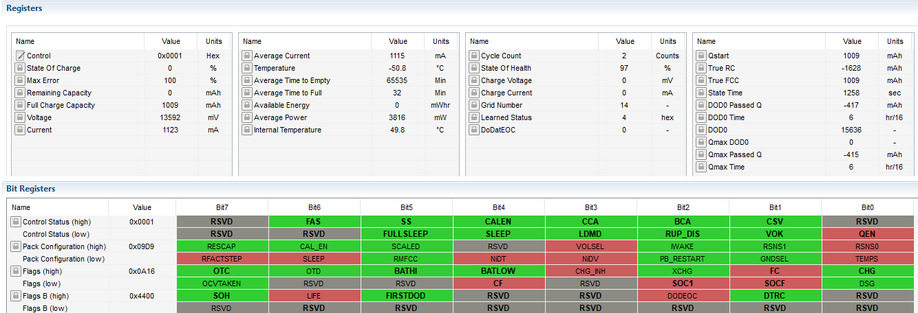
Current register values:

Design capacity: 6400 mAh
Design energy: 81920 mWh ?
Cell charge voltage: 3.475 V
LED_Comm/Alert: /
Number of series Cells: 4
Pack Configuration: VOLSEL is set
Voltage Divider: 17100 mV (Max BATT+)
CC Gain/CC Delta: 100 Ohms?
Load Select: 1 ?
Load Mode: 0 ?
Cell Terminate Voltage: 2.5 V
Quit Current: 50 mA ?
Qmax Cell 0: 1 ?

The chemical id seems to be 0x0444, but bqStudio fails to write this to the gauge with an unknown error code when trying to update.

Nominal system draw current is about 48 mA (this is drawn when the PCB is on and the EV2300 is connected).
The draw in use ranges from 200 mA to spikes of ~2000 A.

Calibrating current always fails, saying I need to apply a discharge current of at least 1A (I don't currently have something that can provide this available).
However after entering -48 mA and clicking away the error message, the gauge on the left indicates the correct value of -48mA...

Calibrating the offsets seems to be working.

Calibrating voltage always fails saying that the value must be in the mV range, but the entered value of 10000mV is somehow not correct...

Temperature calibration (like the others) often fails, but then appears to be correctly set.

Any help would be greatly appreciated. Thanks in advance.

PS It's possible that I bricked a test gauge, since it cannot be detected anymore on the I2C bus. Is it possible to recover it somehow?

  • Hi William,

    Thank you for such a concise post - all of these details are extremely helpful.

    With respect to the version of bqStudio, please update to the latest version of bqStudio by using the confusingly named 'bqstudiotest' link on the bqStudio site. There is a known bug with the bqz file for the 34z100-g1 device in some version of the 1.3.54 release that may prevent proper calibration. The latest version, 1.3.80, from the bqStudioTest link does not exhibit this behavior.

    When updating, please install the new version of bqStudio to a new directory, or fully delete the old version, to ensure no 'old files' wind up in the new installation.

    This new version of bqStudio should ameliorate the calibration issues. Please let me know if the problem persists after the update.


    With respect to gauge compatibility and bqStudio (CRC errors, etc..): this behavior has been seen before and usually coincides with an out of date firmware on the EV2300 itself. What version of firmware are you using on the EV2300? If the firmware is version 3.1.c, it will need to be updated to 3.1.m. The updater and instructions may be found here: e2e.ti.com/.../3225.EV2300FWUpdaterUnprogDev.zip . A second EV2300 will be required to update the first.


    With respect to the pack that is being used - does it currently integrate protection circuitry? If so, does this circuitry 'open' the battery before the terminate voltage of 2.5 V is reached? If so, at what voltage?


    With respect to the register values: most parameters in this gauge are based around single cell values.

    If this is a 4s1p design, the design capacity should be 3200 mAh and design energy should be 10240 mWh for your cells (IFR26650, 3200 mAh, 3.2V).

    Design capacity = battery capacity * # of parallel cells

    Design energy = Design capacity * nominal voltage of 1 cell

    CC Gain / CC Delta should set when performing a current calibration. If its not possible to use an electronic load, please use a power resistor to sink roughly 1 A of current for calibration.


    With respect to potential I2C bus contention, what addresses are currently being used by devices on the bus?

    With respect to possibly bricking the gauge, are you able to get a response (ACK) from the gauge at address AA? If not, please try to get a response from the gauge at address 16. If the device ACKs at address 16, it is in ROM mode. To recover the gauge, please program using the programming tab in bqStudio to program the gauge with the SREC from product folder (the firmware download), found here: www.ti.com/.../sluc580

    With respect to internal temperature sensing, please make sure the TEMPS bit is set properly in the Pack Configuration Register.


    Please let me know if you have any other questions!

    Sincerely,
    Bryan Kahler
  • Bryan,

    Regarding updating the EV2300, indeed it has the factory firmware of version 3.1.c, but it's currently the only one we have. So updating is not possible at this time.

    Protection circuitry:
    We have an overcharge-protection on the PCB, and the battery gauge should check for over-discharging, when it's configured and actually works.

    The MCU has analog pins connected to BAT+ though and can measure the raw voltage value as a fallback. This is what we are currently using during testing to make sure the system stops when the battery reaches a certain voltage. We've never actually fully (dis-)charged the battery, since the gauge was not configured yet.

    So updated the register values should look something like this:

    Design capacity: 3200 mAh
    Design energy: 10240 mWh
    Cell charge voltage: 3.475 V
    LED_Comm/Alert: /
    Number of series Cells: 4
    Pack Configuration: VOLSEL and TEMPS is set
    Voltage Divider: 17100 mV (Max BATT+)
    CC Gain/CC Delta: 100 Ohms?
    Load Select: 1 ?
    Load Mode: 0 ?
    Cell Terminate Voltage: 2.5 V
    Quit Current: 50 mA ?
    Qmax Cell 0: 1 ?

    What should the values of CC Gain / CC Delta be under a 1A load? And should these be reset in production? As you mentioned setting them during a current calibration.

    Another device on the I2C bus has 0xEE as address (old sensor) or 0xEC/ED (new sensor), but these are multiplexed through another I2C chip and shouldn't interfere with the gauge (as they are not connected during testing of the gauge right now).

    With the new bqStudio version, updating the chemistry completed successfully, but with the warning that the target bqz container is old and should be updated.

    Regarding the possible bricked gauge, can I manually send an I2C command through bqStudio, even if it failed to find the gauge?
    In the advanced I2C tab, the address should be 0xAA or 0x16, like you said, but to what register must the data (0x00) be written?

    - William

  • Hi William,

    The EV2300 will need to be updated - we're handling that issue offline.

    With respect to the values of CC Gain / CC Delta, these values are set during calibration by bqStudio. By loading with 1 A, and then in the calibration screen entering the value that is loaded, the gauge will calculate what the values should be to correspond to 1 A actual, instead of the uncalibrated value displayed by the gauge (prior to calibration).

    The CC Gain and CC Delta values are associated typically with the sense resistor. For the bq34z100-g1 evm, this value will be close to '10' for 10 mOhm.

    Which bqz container are you using? The most recent version comes out of the box with the lastest version of bqStudio (bqstudiotest on the bqStudio page, found here: www.ti.com/tool/bqstudio ).

    With regards to the bricked gauge, the answer is yes. In bqStudio, select the bq34z100-g1 gauge when starting up. Just send a command to see if the device will ACK. Please use the advanced communcation tab to see if the device first ACKS a write to 0xAA (meaning the device is in firmware mode and executing firmware). If the device does not ACK a write to 0xAA, please try 0x16. If the device ACKs a write to 0x16, the device is in ROM Mode. It may then be programmed from the programming tab using the default SREC.

    Sincerely,
    Bryan Kahler
  • I ran 2 charge/discharge cycles with a light bulb draining 400mA, and the gauge seems to display the correct drain/charge current and voltage.

    However, it looks like it hasn't learned the battery's properties. I sent "IT_ENABLE" before running these test, but the full charge capacity is displayed as 1 Ah (for the 3.2Ah battery).

    The following readout is from when the battery was completely drained, and plugged in for 10 minutes or so.

    Do I need to perform any additional settings? Does the gauge save it's state to it's internal flash automatically? (because the average values are reset every time)

    The temperature does not seem to be calibrated correctly (-50°C vs 48°C, when room temperature is around 26°C, measured with infrared thermometer on the pack).

    When the documentation says to let the battery relax, am I supposed to disconnect it completely, or do I need to leave the system on (with 47mA nominal drain)?

    Regards

    William

  • Hi William,

    How long did you let the cell rest after full charge?

    How long did you let the cell reset after the full discharge?

    If the cell does not rest, Qmax will not update.

    Please repeat the test, but fully charge the battery and then remove the battery from the charger with no load and allow it to rest for at least 5 hours.

    If this is an LFP cell, please make sure that full charge termination has been met (or the device will require up to 48 hours of reset after a partial charge).

    Discharge the cell to empty and allow the cell to rest again for 5 hours.

    This can be performed out of the system and with the EVM.

    For better temperature readings, please use an external thermistor and set the device for external thermistor usage in the configuration register.

    Sincerely,
    Bryan Kahler