This thread has been locked.

If you have a related question, please click the "Ask a related question" button in the top right corner. The newly created question will be automatically linked to this question.

TPS4H160-Q1: Highside switch TPS4H160 with 3.3V MCU

Part Number: TPS4H160-Q1

Hello Team,

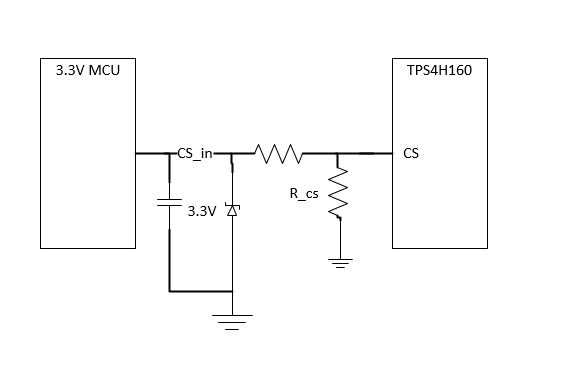
in the Datasheet of TPS4H160-Q1 there is a typical application circuit for a 5V MCU. So far I understand, it is possible to use an 3.3V MCU. Especially, there are no problems for IN1...4, SEH/SEL, DIAG_EN and FAULT signals. What is about the analog current sense? As I understand, I can dimension the Rcs  e.g. for 3.3V maximum linear range Vcs(lin). But in a fault condition there will be Vcs(H) = 4.5V ... 6.5V on this line. Do you have any suggestion how to use current sense with an 3.3V MCU?

Thanks a lot!

Regards  

  • Edit: Correction to Answer

    Hey Andre,

    Yes you can use a 3.3V MCU with this switch. There are two methods to use the 3.3V MCU using the current sense output: voltage divider and Zener clamp.

    1. Voltage Divider.

    In this method, the voltage output from the switch on the current sense pin is divided between two resistors. You can design a ratio that suits your purpose that divides the voltage on the CS pin as needed. This divided voltage can be input into the MCU from the central node.

    2. Zener Clamp

    In this method, a zener clamp is used to regulate any larger voltages. As you stated earlier, you can choose a resistor that ranges 0 to 3.3V in the linear region. When a voltage higher than the zener voltage is seen (assuming 3.3V here), the clamp starts conducting and fixes the voltage to 3.3V thus protecting the MCU