This thread has been locked.

If you have a related question, please click the "Ask a related question" button in the top right corner. The newly created question will be automatically linked to this question.

TLV62130: EMC problem

Part Number: TLV62130

Hello!

I'm use TLV62130 for regulate 3.3V from 12V input.

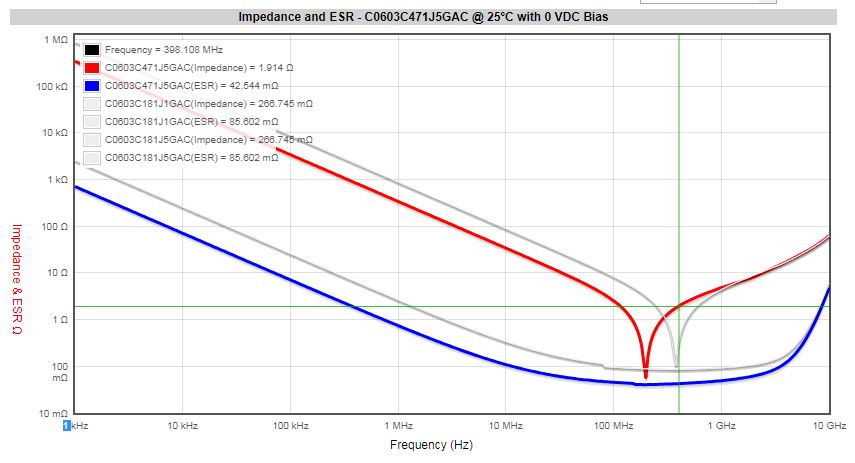
Durring EMC scan I found out wide emission about 400 MHz.

Check with oscilloscope show "ringing" on some pulses at SW pin.

What is really strange, that "ringing" goes away with single one, narrow load point, about 0.25A...

What could be wrong with my design?

With best regards,

Serhiy.

Schematic:

PCB layout: 

SW pin waveform:

Ringing present with load 0.1A … 0.23 A:

NO Ringing with load 0.25 A … 0.255 A:

And Ringing back with load 0.27A … 3 A, but with a little bit bigger amplitude:

  • Hi Serhiy,
    the layout and schematic looks ok. What your measure is expected, you can see ringing at these frequency. In order to mitigate this I would recommend to add a 470pF capacitor (0402) at the input very close to the device. this should reduce the ringing.
  • Hello Sabrina,

    Thank you for answer!

    Sabrina said:
    Hi Serhiy,
    the layout and schematic looks ok. What your measure is expected, you can see ringing at these frequency. In order to mitigate this I would recommend to add a 470pF capacitor (0402) at the input very close to the device. this should reduce the ringing.

    Adding 470pF at input (as I understood from pins 11/12 to pins 15/16) doen't helped in my case - ringing are the same as before.

    Could you recomment different IC with similar parameters and low emission?

    With best regards,

    Serhiy.

  • Hi Shehiy,

    I have a couple of observation about your concerns:

    -How does your measurement look compared against the EMI limits mask ?

    If you see an emission, does not mean your design won't respect the specs. Please compare the measurements with your compliance limits. 

    -Did you make another EMC scan after installing the small cap ? with which probe technique are you making the scopes you shared?

    It could be that you are not using the "pigtail probe", which gives a more transparent frequency response to the scope, and hence that you are not seeing the improvements on the scope. Please try this out and make a new EMC with the cap-mod done. 

    -What is the exact part-number of the 470pF cap you have added on the input? And where did you exactly mount it (please drawa sketch on your layout picture)?

    I am questioning this because it's true that the dimension of the cap influences the parasitics and its bandwidth, but also the material plays a big role. In the graph below in fact you can see the Murata GRM0335C1E471JA01 (cyan curve) has a very small ESR and it's resonance frequency is around 400MHz. This is due to the C0G as dielectric material (which allows the 25V DC voltage rating). On the other side, the GRM011R61A471ME01, which is a 0201 with X5R materia, has higher bandwidth but worse ESR. My suggestion is to try out the first one in case of drastic noise values.

  • Hello Emmanuel,

    Emmanuel Granatello said:

    Hi Shehiy,

    I have a couple of observation about your concerns:

    -How does your measurement look compared against the EMI limits mask ?

    If you see an emission, does not mean your design won't respect the specs. Please compare the measurements with your compliance limits. 

    Emission is about 8-10 dB (around 400Mhz) above of the CISPR 22 B-limit.

    Emmanuel Granatello said:

    -Did you make another EMC scan after installing the small cap ?

    No, I just compared waveforms on "SW" pin: the EMC chamber is far avay...

    Emmanuel Granatello said:

    with which probe technique are you making the scopes you shared?

    It could be that you are not using the "pigtail probe", which gives a more transparent frequency response to the scope, and hence that you are not seeing the improvements on the scope. Please try this out and make a new EMC with the cap-mod done. 

    I'm using Tektronix P6245 active probe. Also, as is wrote, the "Ringing" present only on some pulses, so I see difference, that mean measurement setup is correct.

    Emmanuel Granatello said:

    -What is the exact part-number of the 470pF cap you have added on the input? And where did you exactly mount it (please drawa sketch on your layout picture)?

    I used Kemet C0603C471J1GAC - what I had in my lab...

    Emmanuel Granatello said:

    I am questioning this because it's true that the dimension of the cap influences the parasitics and its bandwidth, but also the material plays a big role. In the graph below in fact you can see the Murata GRM0335C1E471JA01 (cyan curve) has a very small ESR and it's resonance frequency is around 400MHz. This is due to the C0G as dielectric material (which allows the 25V DC voltage rating). On the other side, the GRM011R61A471ME01, which is a 0201 with X5R materia, has higher bandwidth but worse ESR. My suggestion is to try out the first one in case of drastic noise values.

    Could you recommend capacitor in at least 0402 package? 0201 is too small for my design...

    Thank you!

    Serhiy.

  • Hello Serhiy,

    I think we found the reason the capacitor you are using is not making any improvement. From the Kemet website one can get the impeadance, as for Murata's caps, using their K-SIM. In the cap series you are using I only found the 470pF rated for 50V DC. Anyway in the plot below you can see that for the 180pF the 50V and the 100V versions do not differ much (in grey), so I can deduce we can rely on the 470pF 50V for our analysis.

    You can notice that at 400 MHz it's impedance is about 2 ohms, while the ones suggested in my last post present 0.6 ohm (0402 X7R/X6R) and 0.2 ohm (0603 C0G), which is an order of magnitude. I would suggest to use one of these two I have already suggested in the last post.